
Multi-direction position deviation compensating type bearing bush

A multi-directional, bearing technology, which is applied in the direction of couplings, elastic couplings, mechanical equipment, etc., can solve the problems of bearings that cannot be used for transmission equipment, large transmission efficiency loss, and large noise of transmission equipment, so as to achieve direct connection of transmission And effective, rigid, practical effect

Inactive Publication Date: 2019-05-21
浙江诸暨市轴瓦总厂有限公司
View PDF0 Cites 0 Cited by
  • Summary
  • Abstract
  • Description
  • Claims
  • Application Information

AI Technical Summary

Problems solved by technology

[0003] At present, most of the commonly used bearing bushes have high precision requirements, and a bearing bush specification is only suitable for matching shaft connections; and when the bearing bushes are installed, the center position of the drive shaft and the driven shaft installation has a high requirement for the center deviation, otherwise the transmission equipment will be prone to noise. The comprehensive vibration is high, the transmission efficiency loss is large, and the transmission equipment is prone to heat and even stuck, resulting in equipment damage
The bearing bush cannot compensate for the position offset of the transmission equipment caused by external force during work, without affecting the transmission performance

Method used


Image

  • Multi-direction position deviation compensating type bearing bush
  • Multi-direction position deviation compensating type bearing bush
  • Multi-direction position deviation compensating type bearing bush

Examples


Embodiment Construction

[0019] In order to make the object, technical solution and advantages of the present invention clearer, the present invention will be described below through specific implementation examples shown in the accompanying drawings. However, these descriptions are only an example, and are not intended to limit the scope and limitations of the present invention. In addition, in the following description, descriptions of well-known structures and techniques are omitted to avoid unnecessary obscurity or misinterpretation of the concept of the present invention.

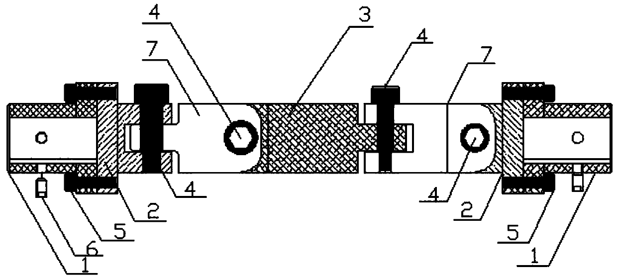
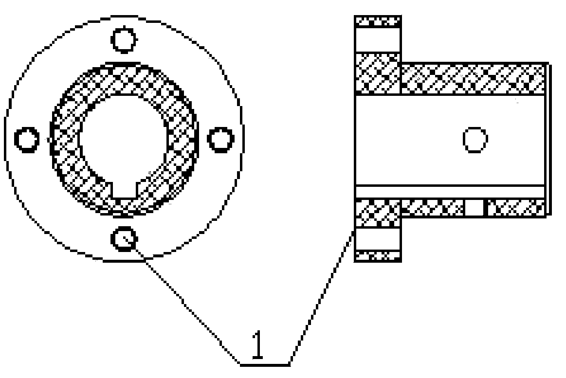
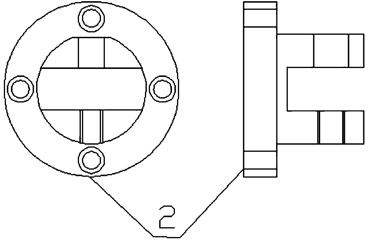
[0020] Such as figure 1 -- As shown in 6, this specific embodiment adopts the following technical scheme: it includes connecting shaft 1, connecting flange 2, transmission rod 3, shaft position screw 4, hexagon socket set screw 5, headless hexagon socket set screw 6 , Movable post 7; the whole set of bearing bushes has two connecting shafts, two connecting flanges, one transmission rod, four shaft screws, eight hexagon socket...


PUM


Abstract

The invention discloses a multi-direction position deviation compensating type bearing bush, and relates to the technical field of bearing bushes. The multi-direction position deviation compensating type bearing bush comprises a connecting shaft, a connecting flange, a transmission rod, an axial screw, an inner hexagonal fastening screw, a headless inner hexagonal fastening screw and a movable connecting rod, wherein an opening groove is formed in one end of the connecting flange; flat wires are arranged at one end of the movable connecting rod, and the other end of the moving connecting rod is provided with an opening groove in the vertical direction; the flat wires at the movable connecting rods are movably matched with the opening groove in the connecting flange; and the opening grooveis movably matched with flat wires of the transmission rod. The position deviation of the bearing bush in a plurality of directions can be compensated through four movable joints. The multi-directionposition deviation compensating type bearing bush is simple in structure, reasonable in design, high in rigidity, low in manufacturing complexity, and low in practicability; and the transmission linkage is direct and effective; the noise is low and the vibration is small during working; the mounting and repairing are convenient; various error in equipment use can be automatically removed through the design; and the practicability and the performance are high.

Description

Technical field: [0001] The invention relates to a bearing bush with wide application range, compensation of up, down, left and right angle position deviation, low noise, simple structure, strong rigidity, convenient maintenance, easy assembly and disassembly, small transmission efficiency loss and long service life, belonging to the technical field of bearing bushes. Background technique: [0002] The bearing bush is a mechanical part used to connect the transmission shaft and the driven shaft so that the two shafts can be selected together to transmit torque. In high-speed power transmission, the effective bearing pad has the functions of buffering, shock absorption and improving the dynamic performance of the transmission mechanism. The bearing pad consists of two halves, which are respectively connected with the driving shaft and the driven shaft. Many general power machines are connected with the working machine by means of bearing bushes. There are many types of bear...

Claims


Application Information

Patent Timeline
IPC IPC(8): F16D3/26
Inventor 杨文彪
Owner 浙江诸暨市轴瓦总厂有限公司
Learn More