
Double-unit pipe shell condenser and use method thereof

A condenser and shell-and-tube technology, applied in the field of double-machine shell-and-tube condensers, can solve the problems of a lot of waste of economic resources and space resources, starting and stopping units, complex structure, etc., to save economic resources and space resources, efficient and fast. The effect of heat exchange and ensuring the quality of condensation

Pending Publication Date: 2019-05-21
广东捷邦节能设备制造有限公司
View PDF0 Cites 2 Cited by
  • Summary
  • Abstract
  • Description
  • Claims
  • Application Information

AI Technical Summary

Problems solved by technology

[0002] The condenser is a component of the refrigeration system, which is a kind of heat exchanger. It can convert gas or vapor into liquid, and transfer the heat in the tube to the air near the tube in a very fast way. Time is wasted due to insufficient utilization of high-power single-unit units. According to market demand, it does not match the single condensing unit. Traditional condensers have many problems, such as complex structure, low heat transfer efficiency, inconvenient operation, and single-unit operation. When the load changes and the unit is started and shut down, the economic and space resources of the enterprise are wasted more, the quality of condensation is difficult to be guaranteed, and it is incompatible with the concept of energy saving, resulting in low efficiency of the use of the condenser. Realization of shell condenser is imperative

Method used


Image

  • Double-unit pipe shell condenser and use method thereof
  • Double-unit pipe shell condenser and use method thereof
  • Double-unit pipe shell condenser and use method thereof

Examples


Embodiment 1

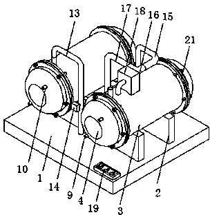
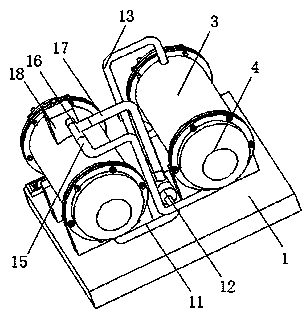
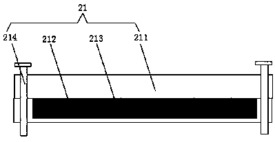
[0021]Embodiment 1: A dual-machine shell-and-tube condenser, including a bottom plate 1, two sets of symmetrically distributed bases 2 are provided on the upper end of the bottom plate 1 to provide bottom support, and the upper end of the base 2 is fixed below the two ends of the arc surface of the condenser tube 3 Connection, both ends of the condensation cylinder 3 are provided with a second connection device 21, the second connection device 21 includes a flange 211, and two symmetrically distributed flanges are provided on the outside of the surface of the condensation cylinder 3 and the inside of the surface of the tube box 4 Disc 211, the threaded holes at the upper ends of two symmetrically distributed flanges 211 are threaded through anti-rust bolts 214, and the inner flange 211 is provided with an annular groove 212 on the side away from the center of the condensation cylinder 3, and the groove of the annular groove 212 is A sealing rubber ring 213 is provided to ensure...

Embodiment 2

[0022] Embodiment 2: A dual-machine shell-and-tube condenser, including a bottom plate 1, two sets of symmetrically distributed bases 2 are provided on the upper end of the bottom plate 1 to provide bottom support, and the upper end of the base 2 is fixed below the two ends of the arc surface of the condenser tube 3 Connection, the two ends of the condensing cylinder 3 are provided with a second connecting device 21, which is convenient for disassembly and maintenance. The flange 211 on the outside of the second connecting device 21 is fixedly connected to the inner surface of the tube box 4, and the inner wall sides of the tube box 4 The tube plate 5 is symmetrically arranged, and the tube plate 5 provides the support of the heat exchange tube 6. The surface of the tube plate 5 is provided with evenly distributed adjustment holes and welded with the outer surface of the heat exchange tube 6, and the heat exchange tube 6 provides the input and exchange of heat material. heat, t...

Embodiment 3

[0023] Embodiment 3: A dual-machine shell-and-tube condenser, including a bottom plate 1, two sets of symmetrically distributed bases 2 are provided on the upper end of the bottom plate 1 to provide bottom support, and the upper end of the base 2 is fixed below the two ends of the arc surface of the condenser tube 3 Connection, both ends of the condensation cylinder 3 are provided with a second connection device 21, the second connection device 21 includes a flange 211, and two symmetrically distributed flanges are provided on the outside of the surface of the condensation cylinder 3 and the inside of the surface of the tube box 4 Disc 211, the threaded holes at the upper ends of two symmetrically distributed flanges 211 are threaded through anti-rust bolts 214, and the inner flange 211 is provided with an annular groove 212 on the side away from the center of the condensation cylinder 3, and the groove of the annular groove 212 is A sealing rubber ring 213 is provided, the sur...


PUM


Abstract

The invention discloses a double-unit pipe shell condenser which comprises a bottom plate. Two sets of symmetrically distributed bases are arranged at the upper end of the bottom plate. The upper endsof the bases and the lower portions of the two ends of the arc face of a condensation barrel are fixedly connected. Second connecting devices are arranged at the two ends of the condensation barrel,and flange plates on the outer sides in the second connecting devices are fixedly connected with the inner side of the surface of a pipe box. Pipe plates are symmetrically arranged on the two sides ofthe inner wall of the pipe box. The double-unit pipe shell condenser is simple in structure, fast and efficient in heat exchange and convenient to operate. A cooling water circulating system is adopted by double units, space is greatly saved, and the units can be started and stopped according to system load changes. When the system load is reduced to a certain degree, one unit can be automatically omitted, and the other unit operates under 60%-100% of the system load; and the economic resource and space resource of enterprises are saved, the condensation quality is guaranteed, and the use efficiency of the condenser is improved. In addition, the invention provides a use method of the double-unit pipe shell condenser.

Description

technical field [0001] The invention relates to the technical field of heat exchange and condensation equipment, in particular to a double-machine shell-and-tube condenser and a method for using the same. Background technique [0002] The condenser is a component of the refrigeration system, which is a kind of heat exchanger. It can convert gas or vapor into liquid, and transfer the heat in the tube to the air near the tube in a very fast way. Time is wasted due to insufficient utilization of high-power single-unit units. According to market demand, it does not match the single condensing unit. Traditional condensers have many problems, such as complex structure, low heat transfer efficiency, inconvenient operation, and single-unit operation. When the load changes and the unit is started and shut down, the economic and space resources of the enterprise are wasted more, the quality of condensation is difficult to be guaranteed, and it is incompatible with the concept of energ...

Claims


Application Information

Patent Timeline
Patent Type & Authority Applications(China)
IPC IPC(8): F25B39/04F25B49/00F28F9/22F28F9/24F28F9/26F28F11/02F28F27/00
CPCY02P80/10
Inventor 范欣杨士举
Owner 广东捷邦节能设备制造有限公司
Learn More