
Electromagnetic brake control device and method

An electromagnetic brake and control device technology, applied in program control, computer control, general control system, etc., can solve problems such as insufficient locking torque, insufficient fixed voltage, brake burnout, etc., to reduce heat aging, low cost, and prolong life. Effect

Inactive Publication Date: 2019-05-21
AEROSPACE INFORMATION
View PDF7 Cites 2 Cited by
  • Summary
  • Abstract
  • Description
  • Claims
  • Application Information

AI Technical Summary

Problems solved by technology

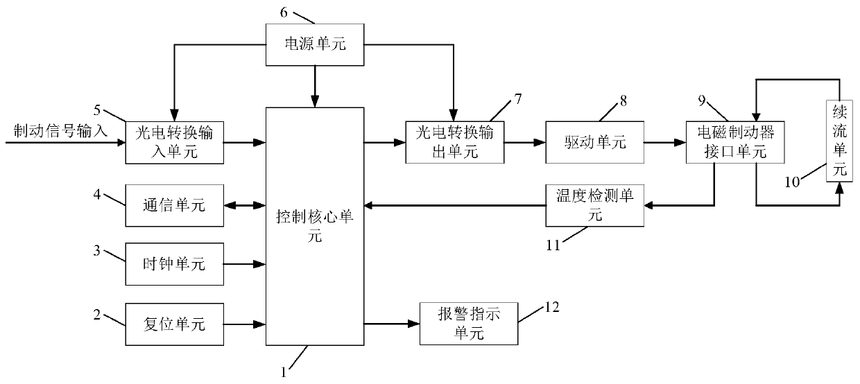
[0003] In order to solve the problems in the background technology that insufficient fixed voltage leads to insufficient locking torque and easily cause the brake to heat up and burn out, the present invention provides an electromagnetic brake control device and method, the device comprising:

Method used


Image

  • Electromagnetic brake control device and method
  • Electromagnetic brake control device and method

Examples


Embodiment Construction

[0037] Exemplary embodiments of the present invention will now be described with reference to the drawings; however, the present invention may be embodied in many different forms and are not limited to the embodiments described herein, which are provided for the purpose of exhaustively and completely disclosing the present invention. invention and fully convey the scope of the invention to those skilled in the art. The terms used in the exemplary embodiments shown in the drawings do not limit the present invention. In the figures, the same units / elements are given the same reference numerals.

[0038] Unless otherwise specified, the terms (including scientific and technical terms) used herein have the commonly understood meanings to those skilled in the art. In addition, it can be understood that terms defined by commonly used dictionaries should be understood to have consistent meanings in the context of their related fields, and should not be understood as idealized or over...


PUM


Abstract

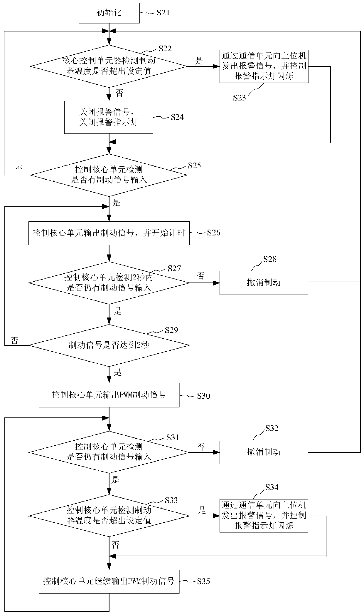
The invention discloses an electromagnetic brake control device and method. The device comprises a control core unit, a clock unit, a photoelectric conversion input unit, a photoelectric conversion output unit and an electromagnetic brake control interface unit, The control core unit is used for receiving a brake input signal and a clock signal and sending a brake output signal; the photoelectricconversion input unit is used for sending the brake input signal to the control core unit; the photoelectric conversion output unit is used for sending the brake output signal to the electromagnetic brake control interface unit; the electromagnetic brake control interface unit is used for driving an electromagnetic brake to attract. The system adopts a control mode of high-pressure suction and low-pressure holding, the high-pressure suction ensures that the electromagnetic brake has larger locking torque at the suction moment, the low-pressure holding can effectively reduce the heating aging of the electromagnetic brake caused by long-time high-pressure suction, and the service life of the electromagnetic brake is greatly prolonged.

Description

technical field [0001] The present invention relates to the technical field of electromagnetic brakes, and more particularly, to an electromagnetic brake control device and method. Background technique [0002] In the current self-service gates at border inspection ports, in order to prevent the gates from being maliciously pushed open, electromagnetic brakes are basically installed on the motors that drive the gates. Once someone pushes the door, the brake is immediately engaged to lock the gate. Most of the existing electromagnetic brake control methods use fixed voltage control, which is prone to insufficient locking torque due to insufficient voltage at the moment of brake pull-in, causing the gate to be easily pushed open. close, it is easy to cause the brake to heat up and burn out. In addition, the existing electromagnetic brake control devices basically do not have a temperature detection function. If the brake is engaged for a long time and the temperature is high...

Claims


Application Information

Patent Timeline
Patent Type & Authority Applications(China)
IPC IPC(8): G05B19/042
Inventor 严兆彬余岸阳邓怒涛
Owner AEROSPACE INFORMATION
Learn More