A power battery cooling device based on the principle of ion wind

A power battery and cooling device technology, applied in corona discharge devices, secondary batteries, battery pack components, etc., can solve the problems of uneven heat dissipation, excessive power consumption, slow cooling speed, etc., to solve the problem of uneven heat dissipation , Increase the thermal conductivity, improve the effect of air supply

Active Publication Date: 2021-08-03
JIANGSU UNIV
View PDF5 Cites 0 Cited by
  • Summary
  • Abstract
  • Description
  • Claims
  • Application Information

AI Technical Summary

Problems solved by technology

[0004] Aiming at the problems of slow cooling speed, excessive power consumption and uneven heat dissipation in the traditional air cooling method, the present invention provides a power battery cooling device with simple structure, low power consumption, no noise and remarkable heat dissipation effect

Method used


Image

  • A power battery cooling device based on the principle of ion wind
  • A power battery cooling device based on the principle of ion wind
  • A power battery cooling device based on the principle of ion wind

Examples


Embodiment 1

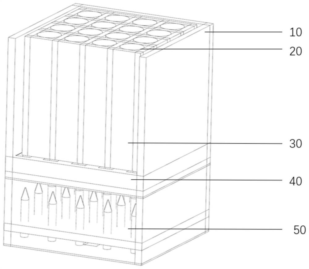
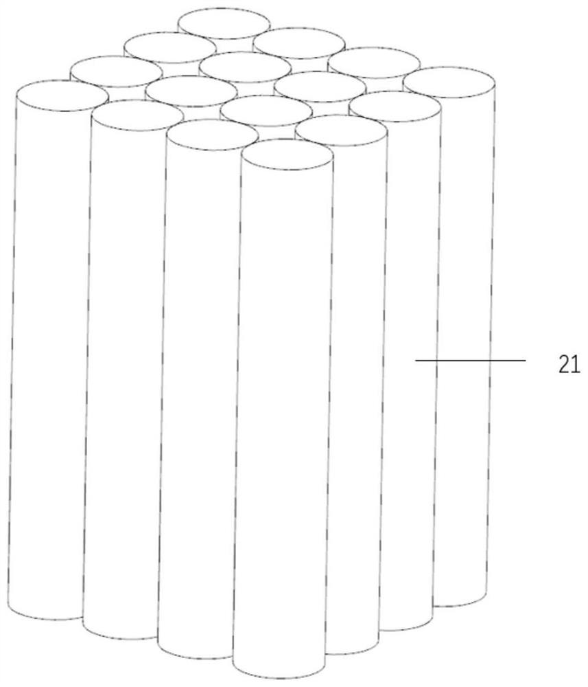
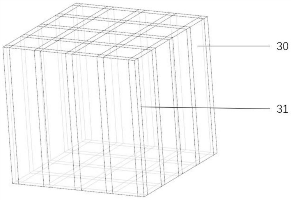
[0028] refer to figure 1 The power battery cooling device based on the ion wind principle of the present invention includes: a housing 10, a power battery module 20, a heat dissipation metal fin module 30, a heat dissipation base 40 and an ion wind heat dissipation module 50, a heat dissipation metal fin module 30, The heat dissipation base 40 and the ion wind heat dissipation module 50 are sequentially arranged inside the cuboid housing 10 .

[0029] Such as Figure 6 As shown, the ion wind cooling module 50 is fixed on the bottom of the housing 10 by bolts, and there are any number of holes on the bottom of the housing 10 to ensure that the ion wind cooling module 50 has a continuous stream of air influx during the working process, so that the corona discharge The process proceeds normally. The ion wind heat dissipation module 50 is located directly below the heat dissipation base 40, the main body of the ion wind heat dissipation module 50 is an ion wind generator, the em...

Embodiment 2

[0034] The emitter 51 of the ion wind generator adopts a wire electrode, and the receiving pole 52 adopts a mesh electrode, such as Figure 7 As shown, the wire electrode adopts metal thin wires, and the metal thin wires are wound along the emitter support 53, and are arranged side by side, and the distance between the wires is 5mm; in order to prevent the distance from being too small or too large, causing the ion wind generator The generated ion wind is small, and the distance L between the wire electrode and the mesh electrode is 5-10mm. Other components of the power battery cooling device are the same as those in Embodiment 1.

Embodiment 3

[0036] The emitter 51 of the ion wind generator adopts a needle electrode, and the receiver 52 adopts a plate electrode, such as Figure 8 As shown, the plate-shaped electrode is a metal plate, and a certain number of through holes are punched on the metal plate, and the through holes can allow ion wind to blow out therefrom to dissipate heat from the power battery module 20 . Other components of the power battery cooling device are the same as those in Embodiment 1.


PUM


Abstract

The invention discloses a power battery cooling device based on the ion wind principle, which comprises an ion wind heat dissipation module, a heat dissipation base, a heat dissipation metal fin module and a power battery module. The main body of the ion wind heat dissipation module is the ion wind generator, the heat dissipation base is designed in the shape of a mesh, the heat dissipation metal fin module is a hollow cuboid heat dissipation metal frame, and the phase change material is stored inside, and the power battery module is placed behind the heat dissipation metal frame , located above the cooling base. When the power battery module generates a large amount of heat, it reaches the temperature required for the phase change of the material, and the phase change absorbs a large amount of heat. At the same time, the ion wind cooling module generates ion wind, which heats the heat dissipation base, power battery module and heat dissipation metal fin module. Heat dissipation. The invention can realize high-efficiency cooling of the power battery under the working conditions of high discharge rate and high working temperature, improve the working reliability of the power battery, and prolong the service life of the power battery.

Description

technical field [0001] The invention relates to a power battery cooling device, in particular to a power battery cooling method and device based on the ion wind principle, and belongs to the technical field of power battery thermal management. Background technique [0002] As a power battery, lithium batteries have the advantages of high specific energy, high specific power, long service life, and wide operating range, and have been widely used in electric vehicles and hybrid electric vehicles. While power batteries are widely used, their safety issues are gradually exposed. Because lithium batteries generate a lot of heat during high-rate charging and discharging, if the heat is not dissipated in time, it will lead to overheating of the battery, which will affect the service life of the battery, and even lead to safety accidents. Therefore, efficient thermal management of power batteries has become an effective method to solve heat dissipation problems. [0003] Most of t...

Claims


Application Information

Patent Timeline
Patent Type & Authority Patents(China)
IPC IPC(8): H01M10/613H01M10/617H01M10/625H01M10/653H01M10/6551H01M10/6563H01M10/6566H01M10/659H01M50/249H01M50/24H01T23/00H01T19/04
CPCY02E60/10
Inventor 蔡忆昔包亚超王静石云飞王姜博
Owner JIANGSU UNIV
Why Eureka
Try Eureka