Packaging antenna, communication device and preparation method of packaging antenna

An antenna and circuit technology, which is applied in the preparation of communication equipment and packaged antennas, and the field of packaged antennas, can solve the problems of ultra-thin communication equipment, limited materials of packaged antennas, limited application scope, etc., and achieves simple packaging and convenient electricity. Connection and installation of flexible effects

Active Publication Date: 2019-05-21
SHANGHAI AMPHENOL AIRWAVE COMM ELECTRONICS CO LTD
View PDF7 Cites 3 Cited by
  • Summary
  • Abstract
  • Description
  • Claims
  • Application Information

AI Technical Summary

Problems solved by technology

For example, in the attached Figure 17 In the existing packaged antenna scheme, the width a of the chip is generally not less than 3 mm, and the width of the AIP antenna is usually not less than 5 mm, and the thickness c of the communication equipment is usually not less than 8 mm. In recent years, communication equipment, especially For mobile terminal communication equipment such as smart phones, in order to meet the market demand, the thickness of the mobile phone is getting thinner and thinner. Obviously, this traditional chip package antenna solution cannot meet the market demand, and has certain restrictions on ultra-thin communication equipment;
[0007] 4) At present, the preferred material for preparing the carrier board is mostly BT resin. The reason is that it is limited by the current process design and the problem of thermal matching with the chip, which leads to limited materials for the preparation of packaged antennas and a technology with limited scope of application. question

Method used


Image

  • Packaging antenna, communication device and preparation method of packaging antenna
  • Packaging antenna, communication device and preparation method of packaging antenna
  • Packaging antenna, communication device and preparation method of packaging antenna

Examples


Embodiment 1

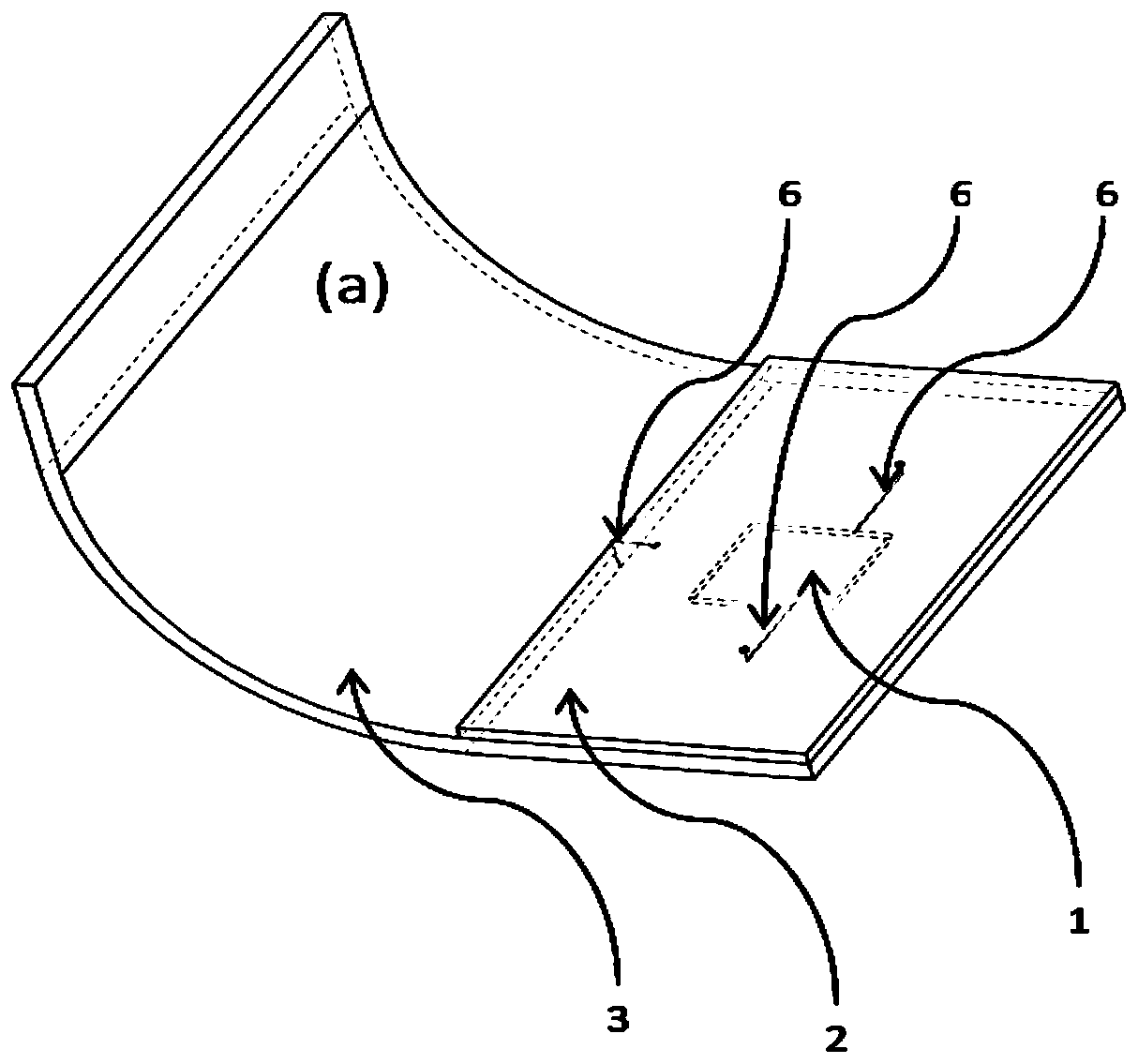
[0065] This embodiment provides a packaged antenna, including: a chip 1; a carrier 2, the surface and inside of the carrier 2 are provided with a data transmission line 6, at least one chip 1 is installed on one side of the carrier 2, and the chip 1 and the data transmission line 6 are electrically connected connection; the covering part 3, the covering part 3 covers the chip 1, and is fixedly connected with the carrier 2, wherein the covering part 3 extends to the outside of the carrier 2 to form a curved surface or a plane; the antenna 4, the antenna 4 is electrically connected to the data transmission line 6 To realize data transmission between the antenna 4 and the chip 1 , the antenna 4 includes one or more radiating surfaces; wherein, the antenna 4 is mounted on the outer surface or inside of the carrier 2 and the cover 3 .

[0066] Specifically, in the antenna package of this embodiment, a single chip 1 can be installed on one side of the carrier 2, and multiple chips 1 ...

Embodiment 2

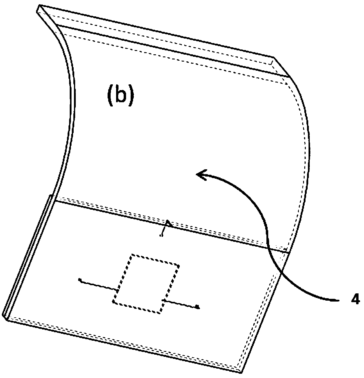
[0084] see figure 1 and figure 2 , this embodiment provides a packaged antenna based on Embodiment 1.

[0085] The packaged antenna of this embodiment includes: a chip 1, a carrier 2, a cover 3, an antenna 4, and a data transmission line 6; wherein, the surface and inside of the carrier 2 are provided with a data transmission line 6, and one side of the carrier 2 is installed with a Chip 1, chip 1 is electrically connected to the data transmission line 6, the covering member 3 covers the chip 1, and is fixedly connected to the carrier 2, one end side of the covering member 3 is extended to form a curved surface, and the antenna 4 is electrically connected to the data transmission line 6, In order to realize data transmission between the antenna 4 and the chip 1 , the antenna 4 is integrally formed with a curved surface, and is attached and installed on the outer surface of the covering member 3 .

[0086] Specifically, see Figure 7 , the packaged antenna of this embodime...

Embodiment 3

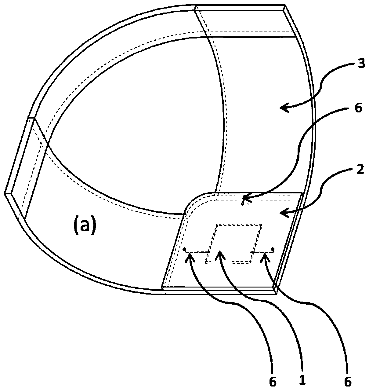
[0088] see image 3 and Figure 4 , this embodiment provides a packaged antenna based on Embodiment 1.

[0089] The packaged antenna of this embodiment includes: a chip 1, a carrier 2, a cover 3, an antenna 4, and a data transmission line 6; wherein, the surface and inside of the carrier 2 are provided with a data transmission line 6, and one side of the carrier 2 is installed with a Chip 1, chip 1 is electrically connected to the data transmission line 6, and the covering part 3 covers the chip 1 and is fixedly connected to the carrier 2. One end side of the covering part 3 is extended to form a curved surface at an angle of 90 degrees as shown in the figure, and the antenna 4 is connected to the data transmission line. The transmission line 6 is electrically connected to realize data transmission between the antenna 4 and the chip 1 , and the antenna 4 is integrally formed on a curved surface and attached to the outer surface of the covering member 3 .

[0090] Specificall...


PUM


Abstract

The invention discloses a packaging antenna. The packaging antenna comprises a chip, a carrier, a coating part and an antenna body, wherein a data transmission line is arranged on the surface of and inside the carrier; at least one chip is mounted on one side surface of the carrier; the chip is electrically connected with the data transmission line; the coating part coats the chip and is fixedly connected with the carrier; the coating part extends towards the outer side of the carrier to form a curved surface or a plane; the antenna body is electrically connected with the data transmission line so as to realize data transmission between the antenna body and the chip; the antenna body comprises one or more radiation surfaces; and the antenna body is mounted on the outer surfaces of or inside the carrier and the coating part. The packaging antenna has the technical characteristics that the packaging is simple, the antenna arrangement is flexible, the radiation angle is wide, and the installation is flexible.

Description

technical field [0001] The invention belongs to the technical field of communication, and in particular relates to a packaged antenna, a communication device and a preparation method of the packaged antenna. Background technique [0002] The structure design of antenna in package (Antenna in Package, AIP) belongs to the integration technology of semiconductor chip and radiating antenna, and is a technology of integrating antenna and semiconductor chip based on packaging materials and processes. The structural design of AIP has received more and more attention. [0003] Judging from the current existing AIP structure design, there are still deficiencies, specifically as follows: [0004] 1) The current carrier is a multi-layer chip structure or a plate structure. Since the antenna can only be arranged on the surface of the chip carrier or the plate carrier, when there are multiple independent antennas forming an antenna array, the radiation surface of each independent antenn...

Claims


Application Information

Patent Timeline
Patent Type & Authority Applications(China)
IPC IPC(8): H01Q1/22H01Q1/24H01Q1/36H01Q1/38H01Q1/50H01Q1/52H01Q21/00H01Q21/06H01L23/66
Inventor 蒋海英吴昊
Owner SHANGHAI AMPHENOL AIRWAVE COMM ELECTRONICS CO LTD
Why Eureka
Try Eureka