
A kind of rubber tire curing method

A curing method and rubber tire technology, applied in the field of rubber tire curing, can solve problems such as water vapor condensation

Active Publication Date: 2021-06-08
HUAIYIN INSTITUTE OF TECHNOLOGY
View PDF3 Cites 0 Cited by
  • Summary
  • Abstract
  • Description
  • Claims
  • Application Information

AI Technical Summary

Problems solved by technology

[0006] However, in the second way, even through the way of adding water vapor externally, there is still water vapor condensation in the external channel

Method used


Image

  • A kind of rubber tire curing method
  • A kind of rubber tire curing method

Examples


Embodiment

[0031] The invention provides a method for curing rubber tires, which includes the step of vulcanizing with a vulcanizing device, and vulcanizing and molding the green tire base through the vulcanizing step.

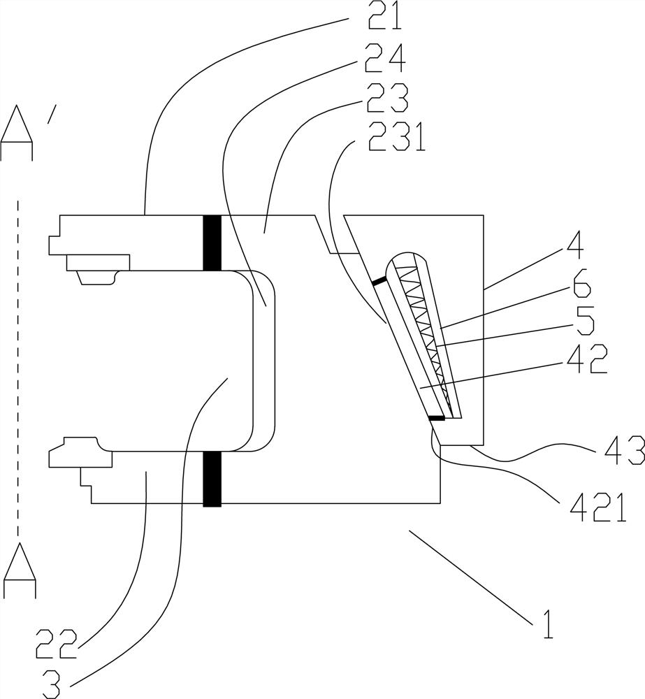
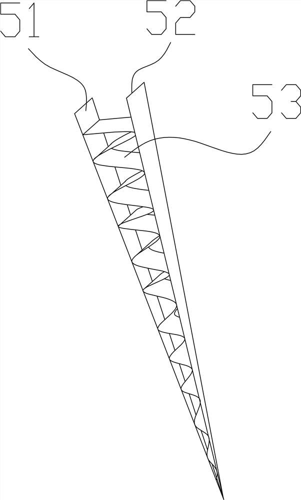
[0032] The structure of the specific vulcanization device 1 is as follows: figure 1 As shown, the vulcanization device 1 is rotationally symmetrical about the axis A-A'. It includes an upper mold 21 located above, a lower mold 22 located below, and an outer mold 23 located on the outside. The outer mold 23 has a frustum-shaped outer surface 231; the inner side of the outer mold 23 is also stacked with The inner mold 24, the upper mold 21, the lower mold 22 and the inner mold 24 form a closed inner cavity 3; the vulcanization device also includes a snap ring 4, which can move in the axial direction and is used for engaging The outer surface 231 of the outer mold 23; the snap ring 4 includes an annular inner pedestal 42 and an outer snap ring 43 with a concave cavity insi...


PUM


Abstract

The present invention relates to a rubber tire curing method, comprising the step of using a vulcanizing device to vulcanize the raw tire blank; the step of vulcanizing and molding includes: S1. Passing heated water into the inner cavity A step of steam heating the inner side of the green tire; S2. A step of feeding heated steam into the outer cavity to assist in heating. The present invention reduces the temperature difference caused by condensed water by means of auxiliary heating, and can solve problems such as insufficient vulcanization or long vulcanization time; by setting a heat conduction element in the cavity of auxiliary heating, the temperature difference during external heating is further reduced, It improves the quality of the tire after molding and avoids the phenomenon of uneven vulcanization.

Description

technical field [0001] The invention relates to the technical field of rubber tire processing, in particular to a rubber tire curing method. Background technique [0002] Pneumatic rubber tires are generally prepared in a laminator, using raw tires that have the ability to flow at a certain temperature, and are vulcanized within a certain period of time by inflating and maintaining a certain pressure. The raw tire is tightly attached to the inner surface inside the mold, and then after shaping treatment, the finished rubber tire with high strength and toughness can be obtained. [0003] There are still certain problems in the prior art. Generally, heating is required in vulcanization equipment, and superheated gas, such as nitrogen or water vapor, is usually used. However, the cost of using nitrogen is high, and water vapor is generally used instead. However, after the heat exchange, the water vapor will condense to produce liquid water, which stays at the bottom. [0004...

Claims


Application Information

Patent Timeline
Patent Type & Authority Patents(China)
IPC IPC(8): B29C33/04B29L30/00
Inventor 蒋彦刘骁陈龙马橼楗高虎山张阳刘雨晴薛甲鹏汪通悦孙全平陈中许兆美
Owner HUAIYIN INSTITUTE OF TECHNOLOGY
Learn More