Full-automatic digital control slip form machine roadbed side ditch construction method

A construction method, the technology of the slip-form machine, applied in the direction of gutters/curbs, roads, roads, etc., can solve the problems of low construction efficiency, low degree of automation, and low efficiency of the construction process

Active Publication Date: 2019-05-24
CHINA RAILWAY 23RD BUREAU GRP NO 1 ENG
View PDF3 Cites 4 Cited by
  • Summary
  • Abstract
  • Description
  • Claims
  • Application Information

AI Technical Summary

Problems solved by technology

[0005] The traditional side ditch construction method has added a lot of manual work, which can no longer meet the requirements of modern construction operations. The traditional side ditch construction method has a low degree of automation, and the cutting seam and walking direction are controlled manually, which cannot achieve long distances. Due to the manual control of the direction, the quality of the concrete layer produced at one time is often not up to the standard, requiring multiple processing by the slipform machine or manual reprocessin

Method used


Image

  • Full-automatic digital control slip form machine roadbed side ditch construction method
  • Full-automatic digital control slip form machine roadbed side ditch construction method
  • Full-automatic digital control slip form machine roadbed side ditch construction method

Examples


Embodiment Construction

[0035] The present invention will be further described in detail below in conjunction with test examples and specific embodiments. However, it should not be understood that the scope of the above subject matter of the present invention is limited to the following embodiments, and all technologies realized based on the content of the present invention belong to the scope of the present invention.

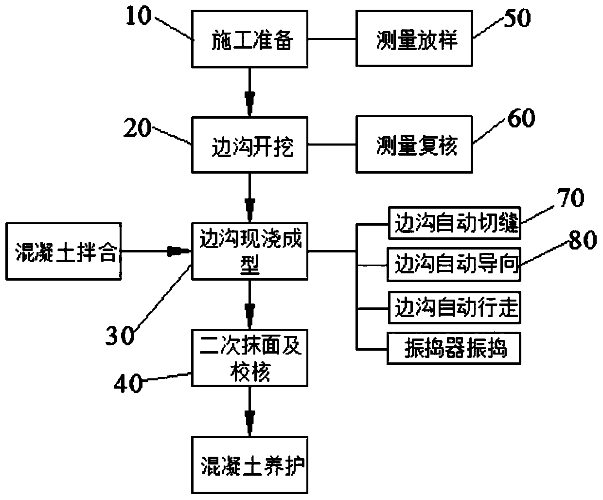
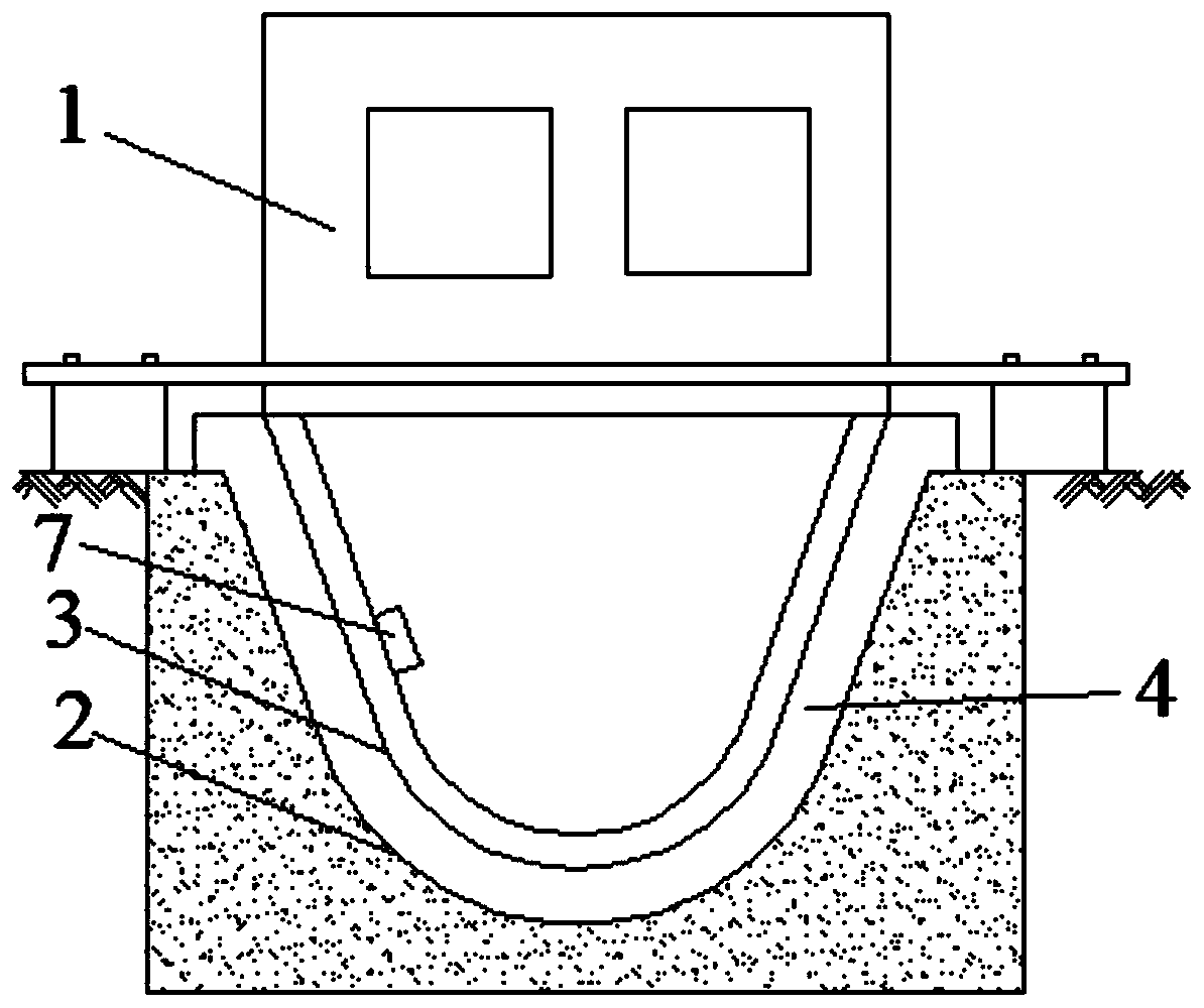
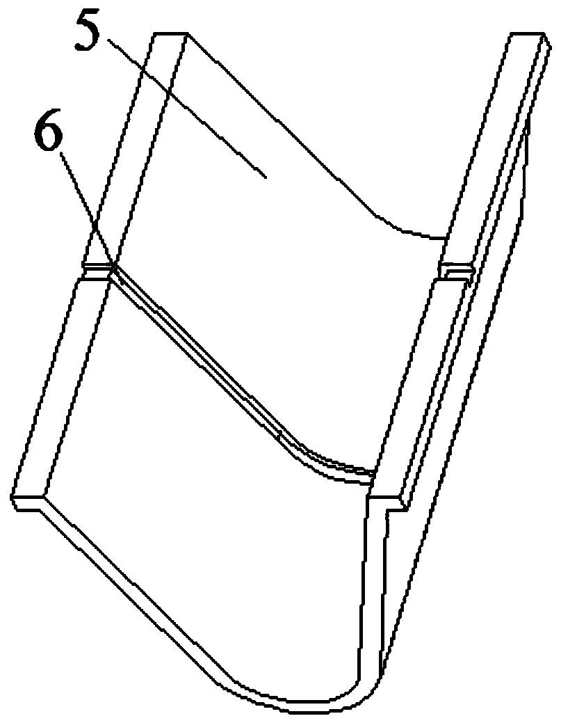
[0036] Specific examples are as follows, such as figure 1 As shown, a fully automatic numerical control sliding form machine subgrade ditch construction method includes a fully automatic numerical control sliding form machine 1 for the construction of side ditch 5, and the fully automatic numerical control sliding form machine 1 includes an outer formwork and a concrete pouring module, When working, the outer formwork surface 3 is adapted to the groove surface 2 of the side ditch 5 to form a cavity 4 for pouring concrete, and the concrete pouring module is used to push concrete into ...


PUM

PropertyMeasurementUnit
Groove widthaaaaaaaaaa
Groove depthaaaaaaaaaa

Abstract

The invention relates to the technical field of the side ditch construction and in particular to a full-automatic digital control slip form machine roadbed side ditch construction method. The construction method comprises the following steps: through installing a full-automatic digital control slip form machine for side ditch construction, wherein the full-automatic digital control slip form machine comprises an outer side template and a concrete pouring module, in a working process, forming a cavity for pouring concrete by matching a surface of the outer side template and a ditch surface of the side ditch, through the concrete pouring module, pushing the concrete into the cavity and extruding to form a concrete layer, wherein the full-automatic digital control slip form machine further comprises a walking module, a guiding module and an automatic joint-cutting module, through the walking module and the guiding module, enabling the full-automatic digital control slip form machine to bewalked along a direction of the ditch, and joint-cutting automatically. The related construction method comprises the steps of construction preparation, side ditch excavation, side ditch cast-in-situforming, secondary plastering and checking. The new side ditch construction method is capable of combining with functions of automatic walking, automatic guiding and automatic joint-cutting, solvinga problem that a traditional side ditch construction method is complicated in process, and improving working efficiency.

Description

technical field [0001] The invention relates to the technical field of side ditch construction, in particular to a roadbed side ditch construction method with a fully automatic numerical control sliding form machine. Background technique [0002] The side ditch is a longitudinal ditch set up on both sides of the road to collect and remove precipitation from the road surface, road shoulder and side slope. the part that can not be lost. The side ditch is the hub connecting the embankment slope and the outer part of the road, acting as a communication "bridge" and playing an extremely important role in many aspects. First of all, the side ditch discharges the precipitation from the road surface and the slope surface, which plays a role in maintaining the stability of the roadbed, which is very important. Secondly, the existence of the side ditch makes the connection between the subgrade and the roadside more perfect, and the beautiful side ditch can greatly increase the lands...

Claims


Application Information

Patent Timeline
IPC IPC(8): E01C11/22E01C19/48
Inventor 丁磊李兆龙马洪明乔军亭张星邢兰涛张兆敏王鹏王玉杰王云鹏
Owner CHINA RAILWAY 23RD BUREAU GRP NO 1 ENG
Why Eureka
Try Eureka