
Fuel gas generator

A technology of gas generators and combustion chambers, which is applied in the direction of burners, burning with various fuels, combustion chambers, etc., to achieve good light transmission, improve compression resistance, and save costs

Pending Publication Date: 2019-05-24
CENT SOUTH UNIV
View PDF0 Cites 3 Cited by
  • Summary
  • Abstract
  • Description
  • Claims
  • Application Information

AI Technical Summary

Problems solved by technology

[0005] In the past, most of the researches were on gas-injection transparent combustion devices, but few involved the discussion of gas-liquid injection transparent combustion devices.

Method used


Image

  • Fuel gas generator
  • Fuel gas generator
  • Fuel gas generator

Examples


Embodiment Construction

[0052] The present invention will be described in further detail below in conjunction with the accompanying drawings.

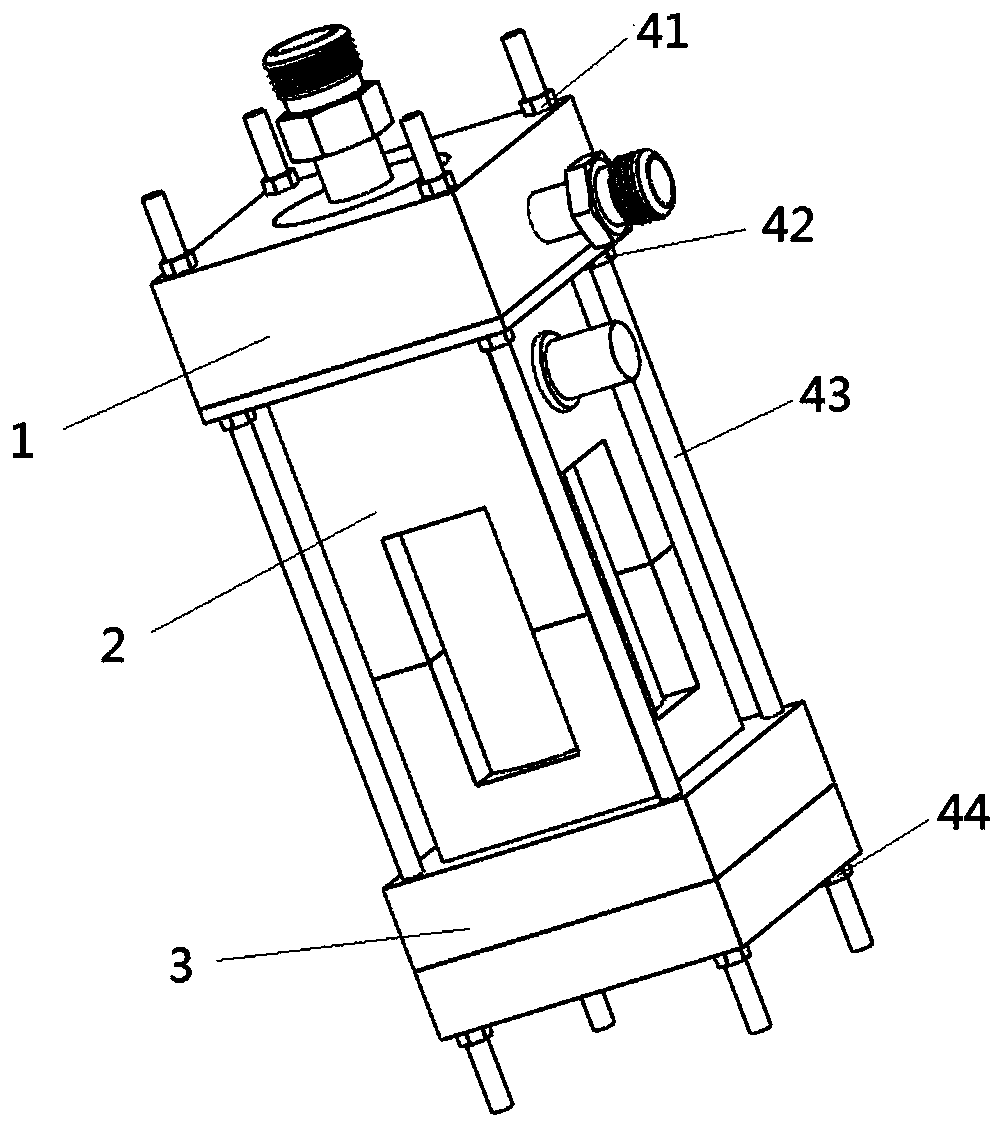
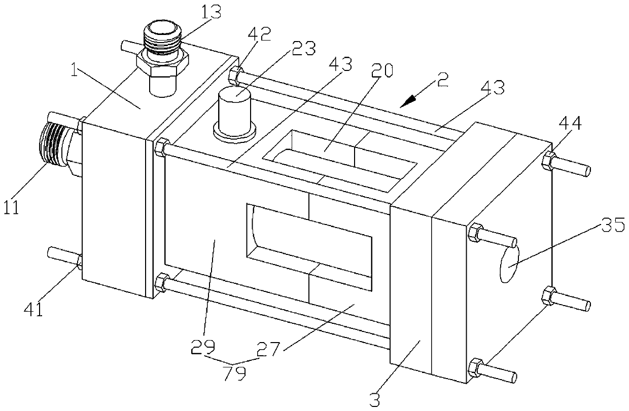
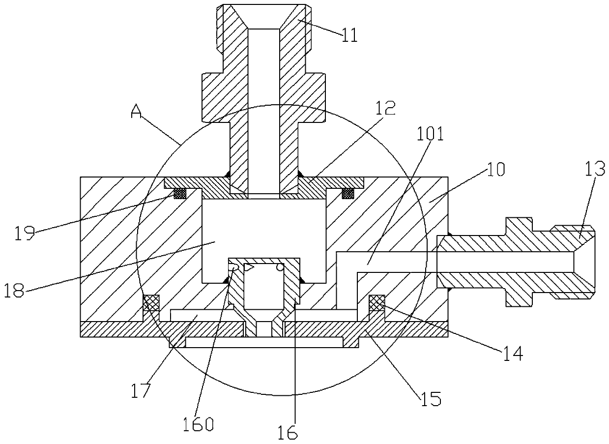
[0053] Embodiments of the present invention provide a small gas generator, such as Figure 1-9 shown, see figure 1 , the gas generator includes from top to bottom: an injector assembly 1, a combustion chamber assembly 2, and a nozzle assembly 3. The injector assembly 1 is arranged at the head of the gas generator, and the nozzle assembly 3 is arranged at the At the tail of the generator, the injector assembly 1 and the nozzle assembly 3 fix the combustion chamber assembly 2 in the middle through the screw 43; the injector assembly 1 and the nozzle assembly 3 of the embodiment of the invention A screw rod 43 of the same size is connected to fix the combustion chamber assembly 2 between the injector assembly 1 and the nozzle assembly 3 . The upper and lower ends of the screw rod 43 cooperate with the first nut 41 and the second nut 44 respectively to apply a ...


PUM


Abstract

The invention provides a fuel gas generator. The fuel gas generator sequentially comprises an injector assembly, a combustion chamber assembly and a spraying pipe assembly from top to bottom, the injector assembly is arranged on the head part of the fuel gas generator, the spraying pipe assembly is arranged on the tail part of the fuel gas generator, and the combustion chamber assembly is fixed tothe middle by the injector assembly and the spraying pipe assembly through threaded rods; the combustion chamber assembly includes a protective sleeve, an igniter and a transparent combustion chamber, and the protective sleeve is arranged on the periphery of the transparent combustion chamber; and the protective sleeve is arranged in a spliced mode and includes an upper half segment protective sleeve and a lower half segment protective sleeve. The fuel gas generator mainly aims at gas-liquid injection combustion and can carry out optical measurement in many directions and means.

Description

technical field [0001] The invention belongs to the field of gas generators, and relates to a gas generator. Background technique [0002] Gas-liquid injection combustion is a common combustion mode for gas generators, and has always been the focus of research at home and abroad. How to make gas-liquid fuel mixed and fully combusted is one of the key technologies of the gas generator. In the experiment, only when the combustion process is accurately measured from multiple directions can more credible experimental data be obtained, so it is very important to study it in depth. [0003] Accurately obtaining the performance parameters of small gas generators used in ground tests is of great significance to the study of aerospace propulsion performance. Not only can it save a lot of cost, but it can also reduce risks, improve safety performance, and contribute to laying the foundation for future research. [0004] The traditional measurement method is mostly contact type, tha...

Claims


Application Information

Patent Timeline
Patent Type & Authority Applications(China)
IPC IPC(8): F23C3/00F23C5/08F23M11/00F23D11/00
Inventor 罗世彬席文雄许德泉戴健袁运飞
Owner CENT SOUTH UNIV
Learn More