
System and method for three-dimensional detection of holes of concrete with cracks

A three-dimensional detection and concrete technology, applied in the direction of measuring device, mechanical measuring device, mechanical depth measurement, etc., can solve the problems of large influence of heat source, unrecognizable, mixing of diffraction signals, etc., and achieve strong operability and strong real-time performance , low cost effect

Pending Publication Date: 2019-05-24
HUNAN CITY UNIV
View PDF0 Cites 2 Cited by
  • Summary
  • Abstract
  • Description
  • Claims
  • Application Information

AI Technical Summary

Problems solved by technology

In addition, the interpretation of these methods requires researchers to have certain professional knowledge, understand the identification and analysis of waveforms or profiles, and cannot intuitively obtain the depth and size of concrete cracks or cavities
[0004] On the other hand, when the existing ultrasonic method is used to detect deep cracks in concrete, the real first wave signal cannot be received. At present, the maximum detection depth can only reach about 0.8m, especially when there is water in the crack, the ultrasonic wave can pass through directly. Cracks, mixed with diffraction signals, increase the difficulty of judgment
The existing infrared thermal imaging method judges concrete defects by analyzing the difference in concrete temperature, which is greatly affected by external heat sources
The existing geological radar method can only detect cavities with a diameter of tens of centimeters or more, and tiny cracks cannot be identified due to the short propagation time
The above method may detect the approximate location of the void, but it cannot meet the high-precision quantitative detection requirements for concrete voids

Method used


Image

  • System and method for three-dimensional detection of holes of concrete with cracks
  • System and method for three-dimensional detection of holes of concrete with cracks
  • System and method for three-dimensional detection of holes of concrete with cracks

Examples


Embodiment Construction

[0027] In order to make the object, technical solution and advantages of the present invention more clear, the present invention will be further described in detail below in conjunction with the examples. It should be understood that the specific embodiments described here are only used to explain the present invention, not to limit the present invention.

[0028] At present, the non-destructive testing techniques used mainly include ultrasonic method, infrared thermal imaging method, and ground radar method. These three methods all have a prerequisite, requiring researchers to have certain professional knowledge and understand the identification and analysis of waveforms or profiles. The shape and size of concrete voids cannot be obtained intuitively. The invention has a simple structure, and compared with the prior art, has the characteristics of low cost, strong real-time performance, high precision, easy operation and the like.

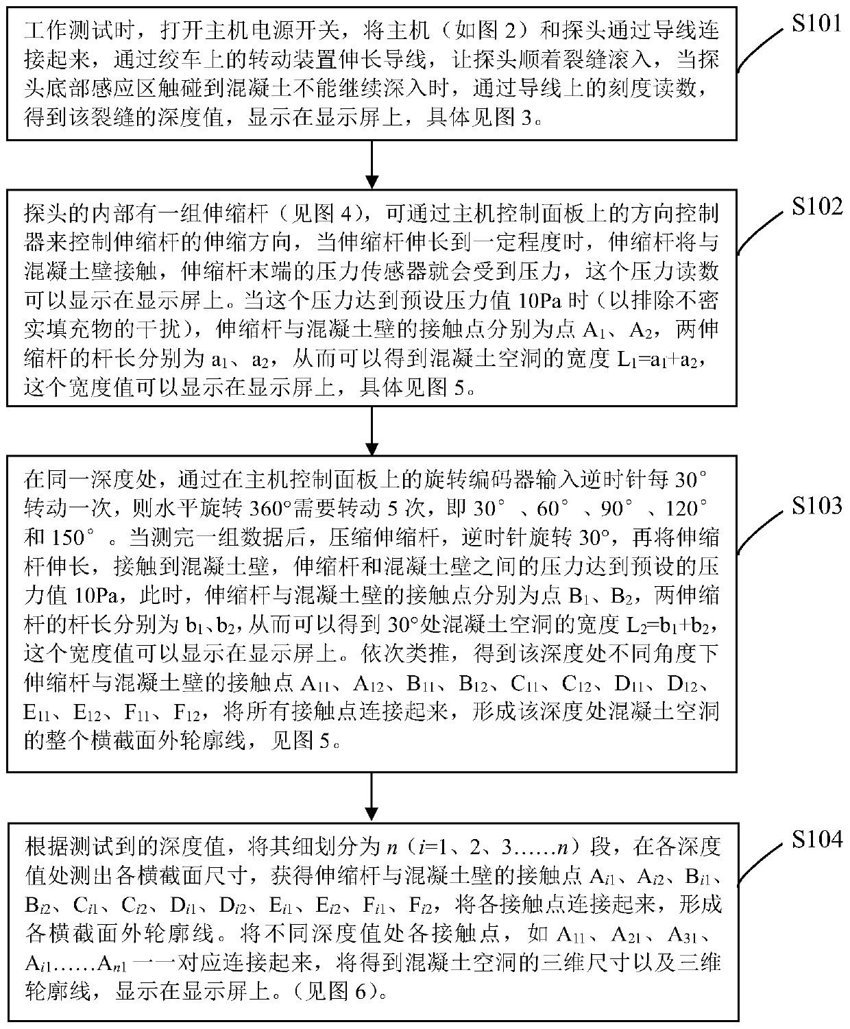
[0029] figure 1 , the three-dimensional ...


PUM


Abstract

The invention belongs to the technical field of non-destructive testing and discloses a system and method for three-dimensional detection of holes of concrete with cracks. A pair of telescopic rods are arranged in a probe, and when the pressure of a pressure sensor at the tail end of each telescopic rod reaches a preset pressure value, contact points of the telescopic rods with a concrete wall arepoints A1 and A2 respectively, lengths of the two telescopic rods are a1 and a2 respectively, and the width L1 of a concrete hole at the position equals to a1+a2; in the same depth, rotating once every 30 degrees anticlockwise is inputted to a rotary encoder, all contact points of the telescopic rods in a certain depth and the concrete wall are obtained, and a whole cross section outline of a concrete hole in the depth is formed; the contact points of the telescopic rods with the concrete wall are obtained to form each cross section outlines; three-dimensional size and three-dimensional outline of the concrete hole are formed. The system and the method have advantages of low cost, high practicality, high accuracy and high operability, and the shape and size of the concrete hole can be obtained quickly and directly.

Description

technical field [0001] The invention belongs to the technical field of non-destructive testing, and in particular relates to a three-dimensional testing method and system for concrete cavities with cracks. Background technique [0002] With the rapid development of the national economy, the state has further strengthened the infrastructure construction, and various buildings have sprung up like mushrooms after rain. As a building material with convenient construction, good performance and low price, concrete is widely used in various constructions. However, concrete is susceptible to cracks and voids due to factors such as external force, steel corrosion, and temperature changes, resulting in a significant decline in the bearing capacity and normal performance of the concrete structure, thereby greatly shortening the design life of the concrete structure. Therefore, it is necessary to detect these cracks and voids, grasp the shape, direction and scale of concrete cracks and...

Claims


Application Information

Patent Timeline
IPC IPC(8): G01B5/20G01B5/02G01B5/18
CPCY02P90/02
Inventor 张胜黎永索李柏付贵海胡达曹鑫
Owner HUNAN CITY UNIV
Features
  • Generate Ideas
  • Intellectual Property
  • Life Sciences
  • Materials
  • Tech Scout
  • Unparalleled Data Quality
  • Higher Quality Content
  • 60% Fewer Hallucinations
Learn More