A kind of mask equipment process debugging method

A debugging method and mask technology, applied in the field of masks, can solve the problems of insufficient use of masks, waste efficiency and high cost, and achieve the effects of high detection and debugging efficiency, consistency assurance, and high use efficiency.

Active Publication Date: 2022-07-15
成都路维光电有限公司
View PDF5 Cites 0 Cited by
  • Summary
  • Abstract
  • Description
  • Claims
  • Application Information

AI Technical Summary

Problems solved by technology

[0004] The technical problem to be solved by the present invention is that when the existing mask is debugged, the cost required is relatively high, and a mask cannot be fully utilized, which is not only wasteful but also inefficient. The purpose is to provide a process debugging method for mask equipment, Solve the problem of mask plate process debugging

Method used


Image

  • A kind of mask equipment process debugging method
  • A kind of mask equipment process debugging method

Examples


Embodiment 1

[0031] like Figures 1 to 2 As shown, a mask equipment process debugging method of the present invention includes the following steps:

[0032] (1) apply photoresist on the mask, and carry out photolithography exposure, development, and etching related procedures respectively to obtain corresponding graphics;

[0033] (2) compare the graphics obtained according to step (1) with the designed graphics, and debug the glue coating equipment, the lithography equipment, the developing equipment and the etching equipment respectively according to the errors of the two;

[0034]In step (1), before applying photoresist and photolithography exposure on the mask, the mask is evenly divided into several equidistant areas, such as the lateral area is A area, B area, C area...X area, etc., The vertical area is A1 area, A2 area, A3 area...A X area, etc., so that the whole is divided into several standard areas; then each area is divided into several areas to be tested, for example, in area ...

Embodiment 2

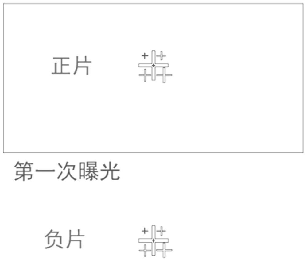
[0040] A process debugging method for mask plate equipment, on the basis of Embodiment 1, the graphics on the area to be tested of the mask plate are the same graphics in the same column and in two adjacent rows from top to bottom, and the graphics to be tested are the same graphics. The two adjacent rows of test areas on the same column and from top to bottom are the positive film area and the negative film area, and the positive film area and the negative film area are symmetrically distributed. After the first exposure, the exposure device was shifted by 500 μm during the second exposure.

Embodiment 3

[0042] A process debugging method for mask equipment, on the basis of Embodiment 2, the cross on each area includes a large cross and four small crosses, and the four small crosses are respectively located in the four areas divided by the large cross. The width of the leg of the big cross is 5 μm, and the width of the legs of the four small crosses are 1 μm, 2 μm, 3 μm, and 4 μm, respectively. The small cross of 1 μm is located in the upper left area of ​​the intersection of the large cross, and the small cross of 2 μm is located at the upper right of the intersection of the large cross. Square area, the small cross of 3 μm is located in the lower left area of ​​the intersection of the large cross, and the small cross of 4 μm is located in the lower right area of ​​the intersection of the large cross. The cross is in the center of each area to be tested.


PUM


Abstract

The invention discloses a process debugging method for mask plate equipment. A mask plate raw material is divided into several areas, and each area is provided with a cross, and the patterns to be tested by lithography equipment, developing equipment and etching equipment are respectively set On the cross on each area; expose the pattern in the first area, and obtain the actual accuracy error of the lithography machine through developing, etching, stripping, cleaning, and measurement processes, and debug the equipment parameters according to the measurement error; After the first test is completed, the mask material is cleaned and then glued; the position of the second exposure file is shifted, and the second exposure is performed, and then the pattern of the second area is tested; the present invention sets the cross The graphics setting and position alignment can effectively detect the graphics with the smallest precision, and the detection and debugging efficiency is higher.

Description

technical field [0001] The invention relates to the field of mask plates, in particular to a process debugging method for mask plate equipment. Background technique [0002] After the mask production equipment is installed, it will enter the process debugging stage. This stage mainly verifies and debugs the equipment, so that the various indicators of the equipment meet the specifications, so as to successfully achieve production. In this stage, the raw material of the mask plate needs to be used, and it is tested and verified whether the capabilities of the coating equipment, lithography equipment, developing equipment, and etching equipment meet the production requirements through the related processes of photoresist, lithography exposure, development, and etching. . After the reticle is subjected to lithography exposure, development, etching and other processes, after the pattern is formed, it will be verified and debugged for the total length precision, local precision,...

Claims


Application Information

Patent Timeline
Patent Type & Authority Patents(China)
IPC IPC(8): G03F1/68G03F9/00G03F7/20
Inventor 林伟
Owner 成都路维光电有限公司
Why Eureka
Try Eureka