A method for obtaining a proton source

An acquisition method and proton source technology, applied in the field of proton source acquisition, can solve the problems that the cost and structure will not be significantly optimized, the technical difficulty is high, and the price is expensive, etc., achieving low cost, high operational flexibility, and simple production Effect

Active Publication Date: 2020-12-18
INST OF HIGH ENERGY PHYSICS CHINESE ACAD OF SCI
View PDF9 Cites 0 Cited by
  • Summary
  • Abstract
  • Description
  • Claims
  • Application Information

AI Technical Summary

Problems solved by technology

Then, use an external electric field to draw out the protons in the plasma to obtain a proton beam; another method is to carry out electron stripping on negative hydrogen ions to obtain protons. This method of using negative hydrogen ions mainly uses ion sources to generate negative The hydrogen ion beam then passes through the stripping membrane, and the electrons of the negative hydrogen ions are stripped and converted into protons. Although the above two solutions can obtain high-intensity proton beams, for general laboratories, the price of these two methods is Expensive and technically difficult, especially using negative hydrogen ion sources, so when using the above two solutions, it is only suitable for large scientific devices, and it is difficult for general laboratories to implement
[0003] Although the patent number is 201711468135.0, the Chinese invention patent application with the patent name of the proton source discloses a proton source and a matching device, although the size of the waveguide and the discharge chamber is reduced accordingly, so that the ion source is also miniaturized accordingly. Compact, but due to the existence of the discharge chamber, the cost and structure of the entire device will not be significantly optimized

Method used


Image

  • A method for obtaining a proton source
  • A method for obtaining a proton source
  • A method for obtaining a proton source

Examples


specific Embodiment approach

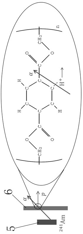
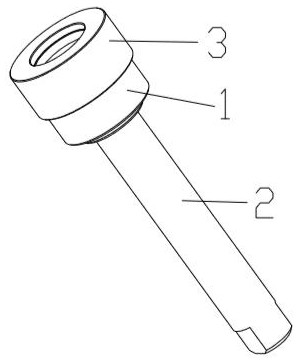
[0014] What needs to be explained in advance is the direction of emission described in this document. Taking the source support device as an example, it is emitted from the smaller end of the source support device to the larger end. Figure 4 For example, the emission direction is from top to bottom.

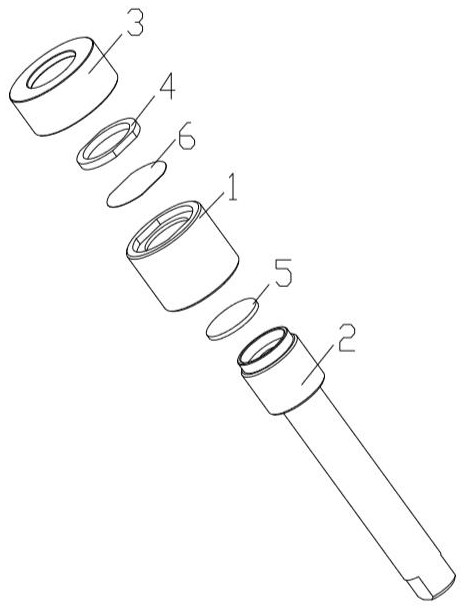
[0015] Such as figure 1 As shown, the working principle of the present invention is a method for obtaining a proton source. The method mainly includes a radiation source 5, a light-transmitting film and a source support device for supporting the radiation source 5 and the light-transmitting film. The radioactive source 5 adopts americium-241 radioactive source 5 as the α source, the light-transmitting film adopts the Mylar film 6, and the source supporting device is used to fix the α source and the Mylar film 6; Installed on the source supporting device in sequence, the surface of the Mylar membrane 6 is parallel to the surface of the α source during installation; when the amer...


PUM


Abstract

The invention relates to the technical field of neutron spallation, in particular to a proton source obtaining method. The method mainly involves a radioactive source, a light-permeating film and a source supporting device used for supporting the radioactive source and the light-permeating film, wherein the radioactive source adopts an americium-241 radioactive source as an alpha source, a Mylar film is adopted as the light-permeating film, and the source supporting device is used for fixing the alpha source and the Mylar film. The alpha source and the Mylar film are installed on the source supporting device in sequence in the transmitting direction, so that the surface of the Mylar film is parallel to the alpha source; americium-241 generates alpha decay, released alpha particles bombardthe Mylar film, so that carbon-hydrogen bonds in the molecular structure of the Mylar film are broken, and free protons are released. The proton source obtaining method is simple in operation, low incost and high in operation flexibility, the generated proton flux can meet general experiment requirements, the method can be used for generating low-energy (keV) proton beam flux, measuring the sections, interacting with matter, of low-energy protons and calibrating energy of a detector.

Description

technical field [0001] The invention relates to the technical field of neutron spallation, in particular to a method for obtaining a proton source. Background technique [0002] So far, the proton is considered to be a stable and non-decaying particle. In physics, the proton is often used to collide with other particles after being accelerated to near the speed of light in an accelerator. This provides extremely important data for studying the structure of the atomic nucleus. However, the easy way to obtain proton sources has always been a worldwide problem. At present, the proton sources in laboratories are mainly used in particle accelerators to generate proton beams. One method is to use ionized hydrogen to generate protons. In this method of using hydrogen, first, hydrogen is injected into a vacuum chamber (generally called a discharge chamber), and then a high voltage is used to break down the hydrogen to ionize hydrogen molecules into protons; thus, A plasma composed ...

Claims


Application Information

Patent Timeline
Patent Type & Authority Patents(China)
IPC IPC(8): G21G4/04
Inventor 李样鲍煜樊睿瑞宁常军王鹏程
Owner INST OF HIGH ENERGY PHYSICS CHINESE ACAD OF SCI
Why Eureka
Try Eureka