
Torque control method for built-in permanent magnet synchronous motor

A permanent magnet synchronous motor and torque control technology, which is applied in the direction of single motor speed/torque control, torque ripple control, motor generator control, etc., can solve the problems of nonlinear motor parameters, difficult to accurately estimate motor torque and Control and other problems, to achieve the effect of strong fitting ability, poor torque fluctuation suppression ability and high precision

Inactive Publication Date: 2019-05-24
GUILIN UNIV OF ELECTRONIC TECH
View PDF3 Cites 3 Cited by
  • Summary
  • Abstract
  • Description
  • Claims
  • Application Information

AI Technical Summary

Problems solved by technology

[0005] In view of the shortcomings of the prior art described above, the purpose of the present invention is to provide a torque control method for a built-in permanent magnet synchronous motor, so as to solve the difficulty in accurately estimating the motor torque due to the nonlinearity and uncertainty of the motor parameters and control issues

Method used


Image

  • Torque control method for built-in permanent magnet synchronous motor
  • Torque control method for built-in permanent magnet synchronous motor
  • Torque control method for built-in permanent magnet synchronous motor

Examples


Embodiment Construction

[0030] Embodiments of the present invention are described below through specific examples, and those skilled in the art can easily understand other advantages and effects of the present invention from the content disclosed in this specification. The present invention can also be implemented or applied through other different specific implementation modes, and various modifications or changes can be made to the details in this specification based on different viewpoints and applications without departing from the spirit of the present invention. It should be noted that, in the case of no conflict, the following embodiments and features in the embodiments can be combined with each other.

[0031] It should be noted that the diagrams provided in the following embodiments are only schematically illustrating the basic ideas of the present invention, and only the components related to the present invention are shown in the diagrams rather than the number, shape and shape of the compo...


PUM


Abstract

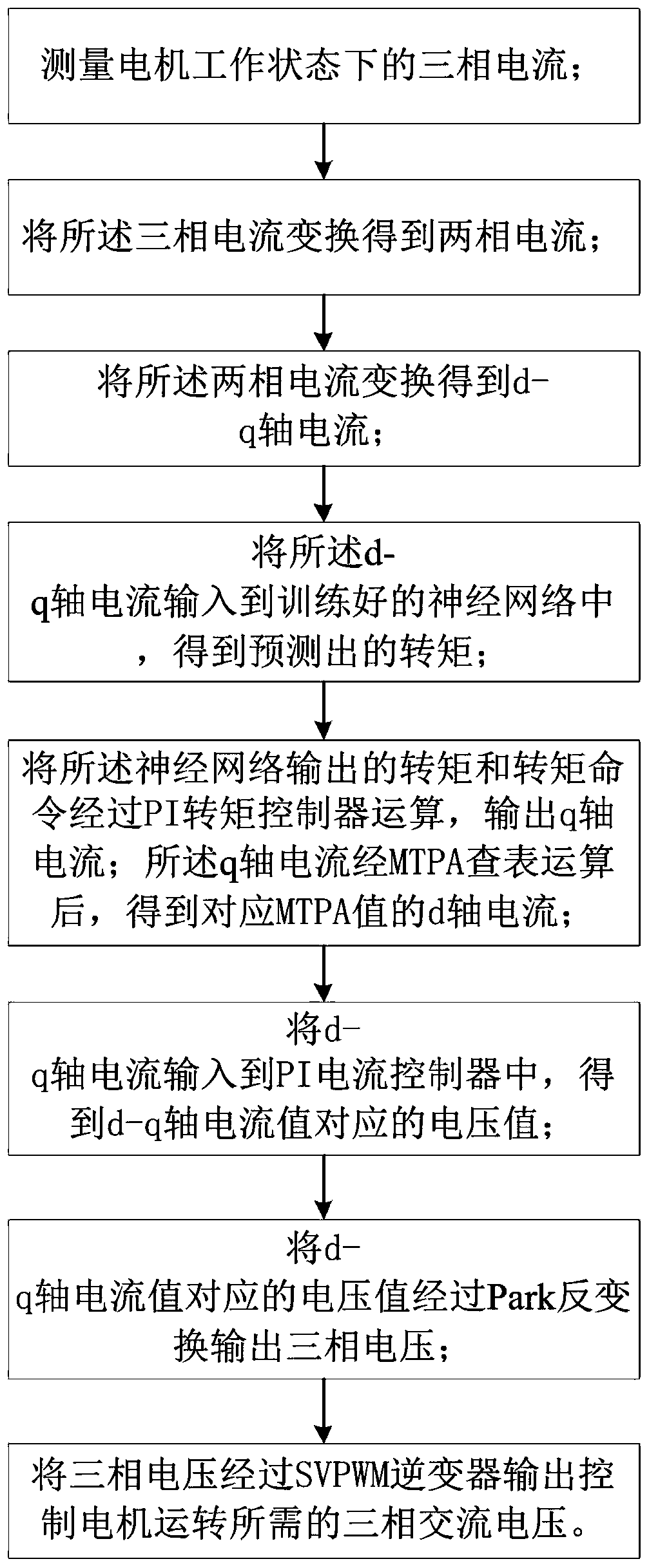
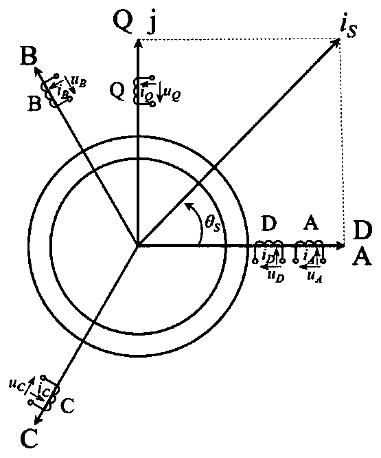
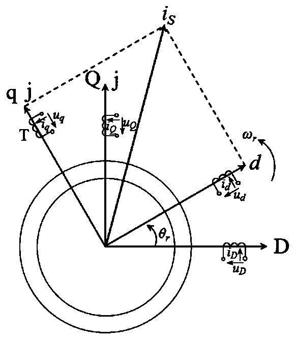
The invention provides a torque control method for a built-in permanent magnet synchronous motor, which comprises steps of measuring the three-phase currents iA, iB, iC of the motor in a working state; converting the three-phase currents iA, iB, iC to obtain the two-phase currents iD, iQ; converting the the two-phase currents iD, iQ to obtain d-axis and q-axis currents id, iq; inputting the d-axisand q-axis currents id, iq into a trained neural network to obtain the predicted torque; calculating the torque output by the neural network and a torque command by a PI torque controller to output the q-axis current; subjecting the q-axis current to MTPA calculation to obtain the d-axis current corresponding to an MTPA value; inputting the d-axis and q-axis currents into a PI current controllerto obtain the voltage values corresponding to the d-axis and q-axis current values; subjecting the voltage values corresponding to the d-axis and q-axis current values to Park inverse transformation to output a three-phase voltage; passing the three-phase voltage through a SVPWM inverter to output a three-phase AC voltage required for the motor operation. The method uses the torque predicted by the LSTM neural network to form a feedforward compensation system, and uses the advantages of good nonlinear fitting ability, high precision and memory ability of historical data of the LSTM neural network.

Description

technical field [0001] The invention relates to the field of motors, in particular to a torque control method for a built-in permanent magnet synchronous motor. Background technique [0002] The built-in permanent magnet synchronous motor (IPMSM) has the characteristics of simple maintenance, light weight, small size, high efficiency, and high power density. It has been widely used in the fields of robots, electric vehicles, CNC machine tools, and inverter air conditioners. Especially in the field of servo transmission, built-in permanent magnet synchronous motors are gradually replacing DC motors and stepping motors and becoming the development direction of servo drives. With the rapid development of power electronics technology, microelectronics technology, sensor technology and motor control theory, the research and popularization and application of built-in permanent magnet synchronous motor control system have received widespread attention from researchers. [0003] Du...

Claims


Application Information

Patent Timeline
Patent Type & Authority Applications(China)
IPC IPC(8): H02P21/00H02P21/13H02P21/20H02P6/08H02P6/10H02P6/34
Inventor 张文涛厉亚强孙天夫熊显名
Owner GUILIN UNIV OF ELECTRONIC TECH
Learn More