Cervical traction device

A technology of cervical traction and traction rope, which is applied in medical science, fractures, passive exercise equipment, etc., can solve the problems of time-consuming and labor-intensive traction, and the traction effect is not obvious, and achieve the effect of extensive industrial value

Pending Publication Date: 2019-05-28
SHENZHEN AONUO MEDICAL TECH CO LTD
View PDF0 Cites 3 Cited by
  • Summary
  • Abstract
  • Description
  • Claims
  • Application Information

AI Technical Summary

Problems solved by technology

[0005] The purpose of the present invention is to provide a cervical traction device to solve the technical problems in the prior art that manual adjustment of the tractor is time-consuming and labor-intensive and the traction effect is not obvious

Method used


Image

  • Cervical traction device
  • Cervical traction device
  • Cervical traction device

Examples


Embodiment 1

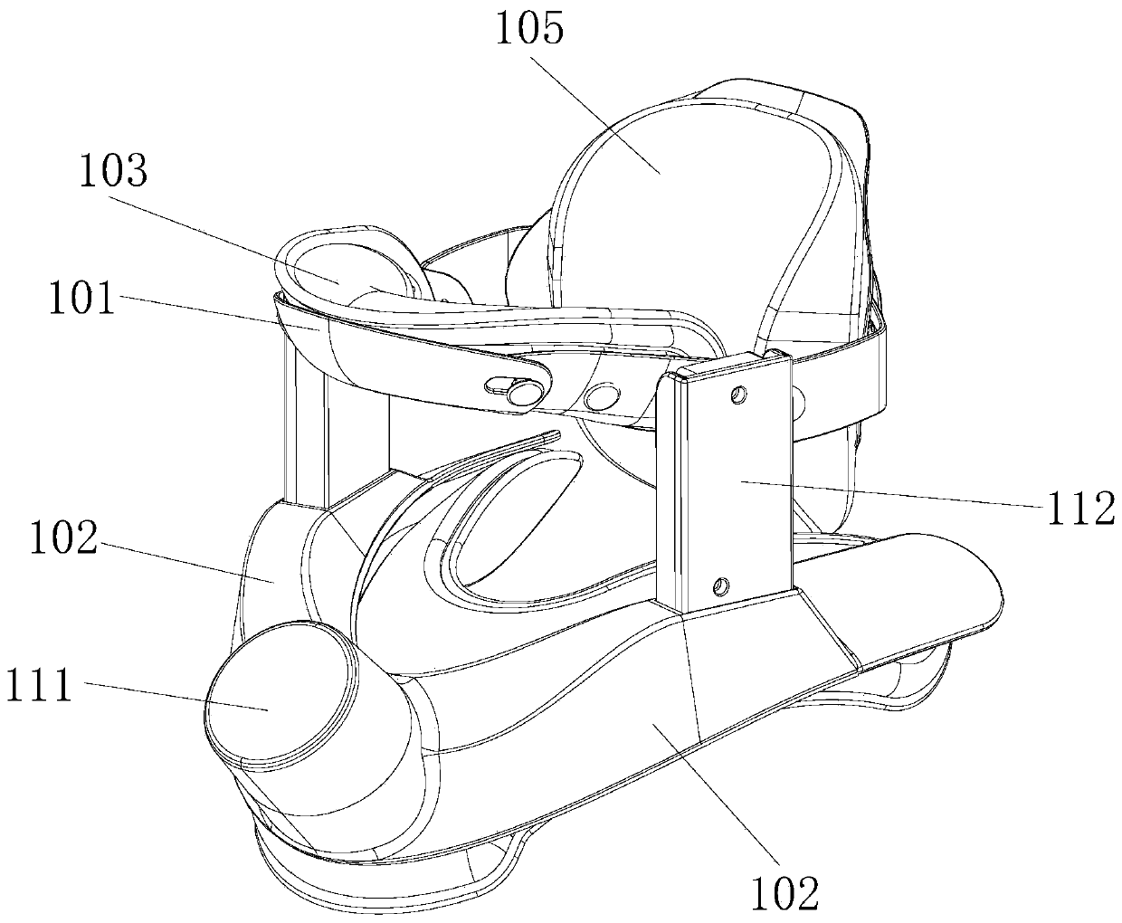
[0037] see Figure 1 to Figure 4As shown, the present embodiment provides a cervical traction device, including a shoulder pressing part, a chin support part 101, a back support part and a power traction mechanism; the pressing shoulder part is connected with the chin support part 101, and the pressing shoulder part Below the chin supporting part 101; the power traction mechanism drives the chin supporting part 101 to move, so that the chin supporting part 101 reciprocates relative to the shoulder pressing part; the back support part of the neck is connected with the chin supporting part 101 for fixing the head neck.

[0038] Based on this structure, the cervical traction device provided in this embodiment fixes the head and neck through the back of the neck support part and the lower jaw support part 101 connected together, so as to limit the head and neck from swinging back and forth. At the same time, the movement of the lower jaw supporting part 101 is driven by the power...

Embodiment 2

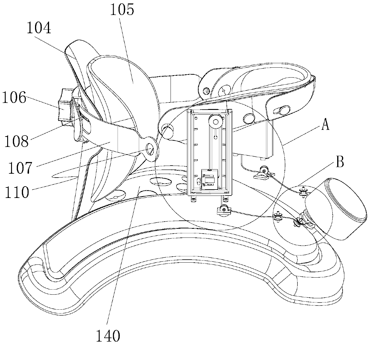
[0067] see Figure 5 As shown, this embodiment also provides a cervical vertebra traction device. The cervical vertebra traction device of this embodiment is an improvement on the basis of the first embodiment, and the technical solutions of the first embodiment also belong to this embodiment. The description will not be repeated here. The same components use the same reference numerals as in the first embodiment, and reference is made to the description of the first embodiment.

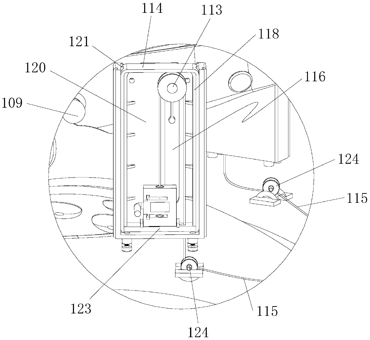
[0068] In some embodiments, the cervical traction device also includes a tension sensor 126 and a controller (not shown), the tension sensor 126 is used to detect the traction pull provided by the power traction mechanism, the tension sensor 126 is connected with the controller, and the controller is connected with the power Traction mechanism connection.

[0069] The tension sensor 126 is disposed on the bottom plate 123 of the first lifting part 114 , and the other end of the traction rope 115 is...

Embodiment 3

[0074] see Figure 6 to Figure 9 As shown, this embodiment also provides a cervical traction device. The cervical traction device of this embodiment describes another implementation of the power traction mechanism, and the technical solutions of the first embodiment also belong to this embodiment , and will not be described again here. The same components use the same reference numerals as in the first embodiment, and reference is made to the description of the first embodiment.

[0075] In some embodiments, the power traction mechanism includes a second driving mechanism 127, a screw rod 128 and a second lifting part, the second driving mechanism 127 is in transmission connection with the screw rod 128, the second lifting part is threadedly connected with the screw rod 128, and the second lifting The part is connected with the jaw supporting part 101; the second driving mechanism 127 drives the screw rod 128 to rotate along its own axis, so that the second lifting part recipro...


PUM


Abstract

The invention relates to the technical field of medical treatment instruments, and particularly relates to a cervical traction device. The cervical traction device comprises a shoulder pressing part,a lower jaw bearing part, a caudal cervical supporting part and a power traction mechanism, wherein the shoulder pressing part is connected with the lower jaw bearing part; the shoulder pressing partis positioned under the lower jaw bearing part; the lower jaw bearing part is driven by the power traction mechanism to be moved to ensure that the lower jaw bearing part can do reciprocation motion relative to the shoulder pressing part; and the caudal cervical supporting part is connected with the lower jaw bearing part and is used for fixing the head and neck parts. The cervical traction devicedisclosed by the invention has the advantages that the head and neck parts can be fixed through the caudal cervical supporting part and the lower jaw bearing part, wherein the caudal cervical supporting part and the lower jaw bearing part are connected together, front-back swinging of the head neck parts can be prevented. Meanwhile, the lower jaw bearing part is driven through the power tractionmechanism to be moved, the cervical vertebrae is drawn upwards, and the phenomena that manual adjustment of a tractor is time-consuming and effort-consuming and a traction effect is not obvious are alleviated.

Description

technical field [0001] The invention relates to the technical field of medical instruments, in particular to a cervical traction device. Background technique [0002] Cervical spondylosis is a general term for cervical osteoarthritis, hypertrophic cervical spondylitis, cervical nerve root syndrome, and cervical disc herniation. It is a disease based on cervical degenerative pathological changes. Due to the long-term strain of the cervical spine, the physiological forward flexion of the cervical spine disappears, straightens, and even reverse flexion of the cervical spine occurs. Bone hyperplasia, intervertebral disc herniation, and ligament hypertrophy compress the spinal cord, nerve roots, and vertebral arteries. [0003] Traction is the most basic therapy for the prevention and treatment of cervical spondylosis. There are two main types of traction therapy: one is horizontal traction, which requires a specific traction bed, and the patient lies on the bed for traction trea...

Claims


Application Information

Patent Timeline
Patent Type & Authority Applications(China)
IPC IPC(8): A61F5/042A61H1/02
Inventor 李振宇
Owner SHENZHEN AONUO MEDICAL TECH CO LTD
Why Eureka
Try Eureka