

Heat tube heating plate
A heating plate and heat pipe type technology, which is applied in heating devices, lighting and heating equipment, heat exchange equipment, etc., can solve the problems that the heating plate affects heat conduction and heat transfer, the internal structure of the heating plate is complicated, and it is not easy to clean and descale. Achieve the effect of improving material drying efficiency, optimizing material drying effect, and reducing loss
- Summary
- Abstract
- Description
- Claims
- Application Information
AI Technical Summary
Problems solved by technology
Method used
Image

Examples
Embodiment Construction
[0045] Below in conjunction with accompanying drawing, the present invention will be further described:
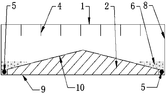
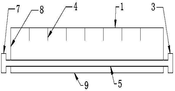
[0046] Such as figure 1 , figure 2 A heat pipe type heating plate shown includes a top plate 1 , a bottom plate 2 , a heat conducting strip 4 , a heating device 5 , a heat conducting working fluid 6 , and a side plate 8 .
[0047] The length of the heat pipe type heating plate is 8500mm, the width is 800mm, and the thickness is 118mm.
[0048] The material of the top plate 1 and the side plate 8 is a metal plate, and the material of the bottom plate 2 is a metal block.
[0049] There is no insulation layer on the outside of the side plate 8.
[0050] The shape of the side plate 8 is L-shaped, the plate surface of the lower end of the side plate 8 is folded in an L shape, and the upper end of the side plate 8 is straight.
[0051] The cross-section of the bottom plate 2 is triangular.
[0052] The space between the upper surface 10 and the lower surface 9 of the base ...
PUM
| Property | Measurement | Unit |
|---|---|---|
| Length | aaaaa | aaaaa |
| Width | aaaaa | aaaaa |
| Thickness | aaaaa | aaaaa |
Abstract
Description
Claims
Application Information