Optical receiving module, and laser radar system

A light receiving module and light receiving technology, applied in the field of laser detection, can solve the problems of increasing the influence of ambient light, low transmittance of signal light, and large influence of transmittance, etc., to improve the intensity, enhance the suppression effect, and increase the reflection rate effect

Active Publication Date: 2021-10-22
HESAI TECH CO LTD
View PDF12 Cites 25 Cited by
  • Summary
  • Abstract
  • Description
  • Claims
  • Application Information

AI Technical Summary

Problems solved by technology

The data of the laser radar will be affected by the ambient light. In order to suppress the ambient light, the existing laser radar system usually uses a transmissive narrow-band interference filter. However, this solution will bring some problems, such as the transmissive interference filter The transmittance is greatly affected by the incident angle, and the transmittance of the signal light incident at a large angle will be very low, so that the laser radar cannot receive the signal incident at a large angle, unless the transmittance bandwidth of the transmissive interference filter is relaxed , but this again increases the effect of ambient light

Method used


Image

  • Optical receiving module, and laser radar system
  • Optical receiving module, and laser radar system
  • Optical receiving module, and laser radar system

Examples


Embodiment Construction

[0033] In order to make the above objects, features and beneficial effects of the present invention more comprehensible, specific embodiments of the present invention will be described in detail below in conjunction with the accompanying drawings. Each embodiment in this specification is described in a progressive manner, each embodiment focuses on the difference from other embodiments, and the same or similar parts of each embodiment can be referred to each other.

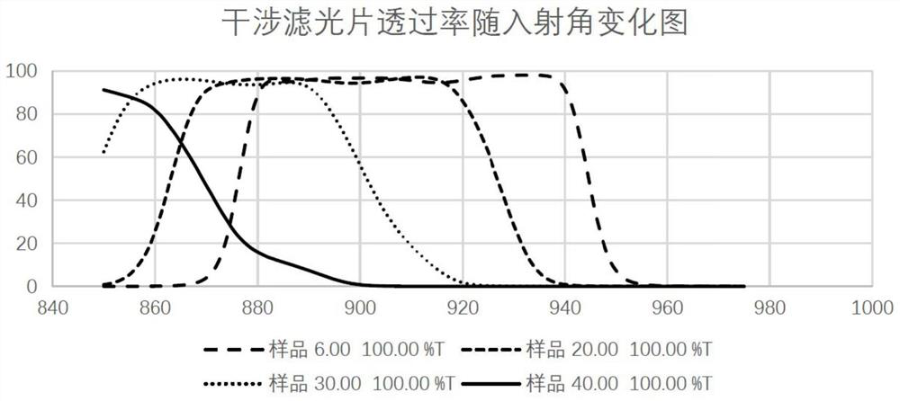
[0034] As mentioned in the background, there are some problems in the existing transmission interference filter for suppressing ambient light. refer to figure 1 , figure 1 It is a graph of the transmittance curve of an interference filter changing with the incident angle, specifically showing the transmittance curves of the interference filter when the incident angle is 6 degrees, 20 degrees, 30 degrees, and 40 degrees. Depend on figure 1It can be seen that the transmittance curve of the interference filter mov...


PUM


Abstract

The present invention provides an optical receiving module and a laser radar system, the optical receiving module includes: an optical transmission sub-module and a detection sub-module sequentially arranged along the receiving optical path; the optical transmission sub-module is suitable for receiving, filtering, and transmitting light beams, the light beams include signal light; and the detection sub-module is adapted to receive and detect the light beams transmitted by the light transmission sub-module; wherein, the light transmission sub-module and / or the detection sub-module includes absorption type substrate, the absorption type substrate is suitable for absorbing at least light in a predetermined wavelength band outside the wavelength range of the signal light. The laser radar system includes: a light emitting module, adapted to emit a detection laser beam to the outside; and the light receiving module, adapted to receive and detect an echo signal of a laser beam formed by reflecting the detection laser beam from the outside. The light receiving module and the laser radar system of the embodiments of the present invention can suppress ambient light, increase the intensity of obliquely incident signal light at a large angle, and improve the signal-to-noise ratio.

Description

technical field [0001] The invention relates to the technical field of laser detection, in particular to a light receiving module and a laser radar system. Background technique [0002] Lidar is an advanced detection method that combines laser technology with photoelectric detection technology. Lidar is widely used in autonomous driving, transportation and communication, drones, intelligent robots, energy Security testing, resource exploration and other fields. [0003] The data quality of lidar is an important criterion to measure its performance. The data of the laser radar will be affected by the ambient light. In order to suppress the ambient light, the existing laser radar system usually uses a transmissive narrow-band interference filter. However, this solution will bring some problems, such as the transmissive interference filter The transmittance is greatly affected by the incident angle, and the transmittance of the signal light incident at a large angle will be ...

Claims


Application Information

Patent Timeline
Patent Type & Authority Patents(China)
IPC IPC(8): G01S7/481
Inventor 杨金涛向少卿
Owner HESAI TECH CO LTD
Why Eureka
Try Eureka