A piezoelectric stack-driven transfusion device

An infusion device and piezoelectric stacking technology, applied in the field of medical devices, can solve the problems of blood backflow, increase the burden on the heart, and have no therapeutic effect, and achieve the effects of increasing gas pressure, facilitating movement and portability

Active Publication Date: 2021-05-28
ZHEJIANG NORMAL UNIVERSITY
View PDF25 Cites 0 Cited by
  • Summary
  • Abstract
  • Description
  • Claims
  • Application Information

AI Technical Summary

Problems solved by technology

This infusion mode will bring many problems in actual use: the flow rate is adjusted manually, and the flow control accuracy is not enough; the infusion bottle needs to be held high by others when the patient walks or goes to the toilet, which is inconvenient to move and the height of the infusion bottle is not high enough. Make the blood flow back; patients or nurses need to be guarded for a long time, if the infusion is not found in time, it may cause accidents; the liquid medicine is in contact with the air, and the ambient air may be polluted when the air is unclean
In addition to the above direct problems, sometimes the infusion time is shortened by reducing the amount of solution, speeding up the infusion speed, etc., which not only increases the burden on the heart, but also affects the therapeutic effect: intramuscular injection and subcutaneous injection in a relatively short period of time. The biggest disadvantage of injecting into muscle or subcutaneous is that the blood drug concentration varies greatly within an injection cycle, which is not conducive to the effective absorption and utilization of drugs, because most drugs have a better concentration range in the human body, and when the drug concentration is too high Has toxic side effects, if it is too low, it will have no therapeutic effect

Method used


Image

  • A piezoelectric stack-driven transfusion device
  • A piezoelectric stack-driven transfusion device
  • A piezoelectric stack-driven transfusion device

Examples


Embodiment Construction

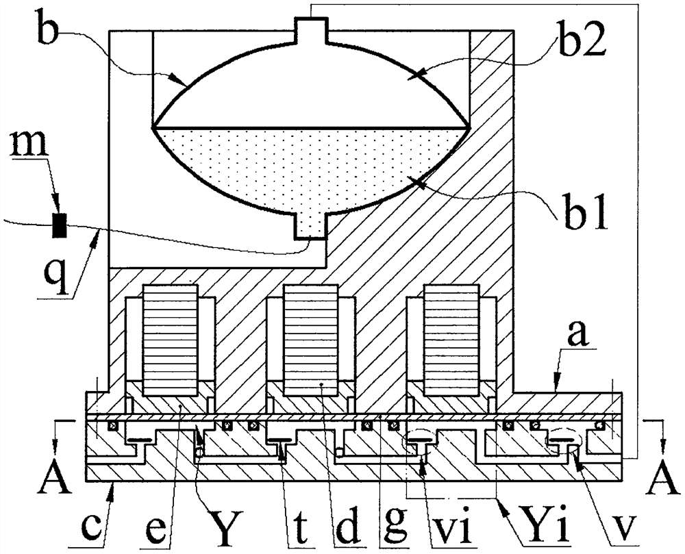
[0014] The top of the base c is provided with an inlet hole c1, a cavity c3 communicating with the outlet hole c7 through the outlet cavity c6, and at least two body cavity groups Ci composed of body cavities c2. The number decreases in turn; one body cavity c2 in each body cavity group Ci is provided with an inlet c4 and an air outlet c5, and the other body cavities c2 are only equipped with a ventilation hole c8; the inlet c4 and the inlet c1 in the leftmost body cavity group Ci Connected, the air outlet c5 in the rightmost body cavity group Ci communicates with the outlet cavity c6; the air outlet c5 in the same body cavity group Ci communicates with the ventilation hole c8 through the communication hole c9, and the inlet c4 in the two adjacent body cavity groups Ci It communicates with the air outlet c5; the inlet cavity c4 and the outlet cavity c6 and the valve plate t installed in it constitute the inlet valve vi and the outlet valve v respectively, and the valve plate t ...


PUM


Abstract

The invention relates to a piezoelectric stack-driven transfusion device, which belongs to the field of medical equipment. The top of the base is provided with an inlet hole, a cavity communicating with the outlet hole through the outlet cavity, and at least two body cavity groups composed of body cavities; only one body cavity in each body cavity group is provided with an inlet cavity and an air outlet hole, and the other body cavities are only provided with Ventilation hole; the main body crimps the diaphragm on the base, and the bottom of the main body is provided with guide hole groups and guide holes equal to the body cavity group and the number of body cavities contained therein. The guide holes are equal in diameter to the body cavity and symmetrically arranged on both sides of the diaphragm. It forms a compression chamber with the body cavity and the inlet valve; the compression chambers in the same body cavity group are connected in parallel to form a compression chamber group, and each compression chamber group is connected in series; the piezoelectric stack in the guide hole presses the piston on the diaphragm; the cavity on the top of the main body is equipped with A medicine bag composed of a medicine chamber and an air chamber; the air chamber communicates with the outlet hole through the air delivery pipe, and a flow valve and a needle are installed on the infusion pipe of the medicine chamber; The diaphragm deforms in the opposite direction.

Description

technical field [0001] The invention belongs to the field of medical equipment, and in particular relates to a piezoelectric stack-driven transfusion device. Background technique [0002] Existing injections mainly include intravenous injection, intramuscular injection and subcutaneous injection. Intravenous injection is also called infusion drug administration. Most of the existing infusion devices are composed of infusion bottles, infusion tubes and infusion stands. This infusion mode will bring many problems in actual use: the flow rate is adjusted manually, and the flow control accuracy is not enough; the infusion bottle needs to be held high by others when the patient walks or goes to the toilet, which is inconvenient to move and the height of the infusion bottle is not high enough. Make the blood flow back; the patient or the nursing staff need to watch for a long time, if the infusion is not found in time, it may cause an accident; the liquid medicine is in contact w...

Claims


Application Information

Patent Timeline
Patent Type & Authority Patents(China)
IPC IPC(8): A61M5/155A61M5/168
Inventor 李建平吴正韬苏玲刘盼盼阚君武王进曾平
Owner ZHEJIANG NORMAL UNIVERSITY
Why Eureka
Try Eureka