Medical high-speed centrifuging equipment and centrifugal rotor

A centrifugal rotor, high-speed technology, applied in the field of medical testing, can solve the problems of increasing the working energy consumption of the centrifuge, the centrifugal separation effect, difficulty in sampling, and trouble, so as to improve the sampling efficiency and sampling data accuracy, and facilitate the disassembly and assembly of the hanging cup. Effect

Inactive Publication Date: 2019-05-31
王加皮
View PDF6 Cites 1 Cited by
  • Summary
  • Abstract
  • Description
  • Claims
  • Application Information

AI Technical Summary

Problems solved by technology

However, in the actual operation process, the existing centrifuge rotor has the following technical drawbacks. First, the sampling tube on the existing centrifuge rotor is basically fixed as one with the centrifuge rotor, so that it cannot A variety of sample agents are used for sampling, and the sampling tube is not easy to disassemble and assemble, which is troublesome; second, the sampling tube is basically placed upright, and when it is centrifuged at high speed, all the particles inside the liquid are deposited on the side wall of the sampling tube It is not easy to sample after the end, which may lead to inaccurate sampling data. Third, the sampling tube changes from a vertical state to a horizontal state during high-speed operation, which creates a lot of noise and wind resistance, which will increase the energy consumption of the centrifuge and the centrifuge. seperate effect

Method used


Image

  • Medical high-speed centrifuging equipment and centrifugal rotor
  • Medical high-speed centrifuging equipment and centrifugal rotor
  • Medical high-speed centrifuging equipment and centrifugal rotor

Examples


Embodiment Construction

[0024] In order to make the present invention more obvious and understandable, the detailed description is as follows in conjunction with the accompanying drawings.

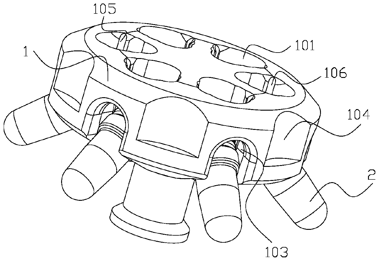
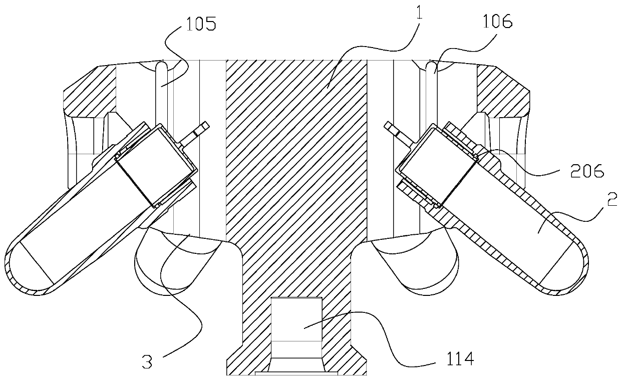
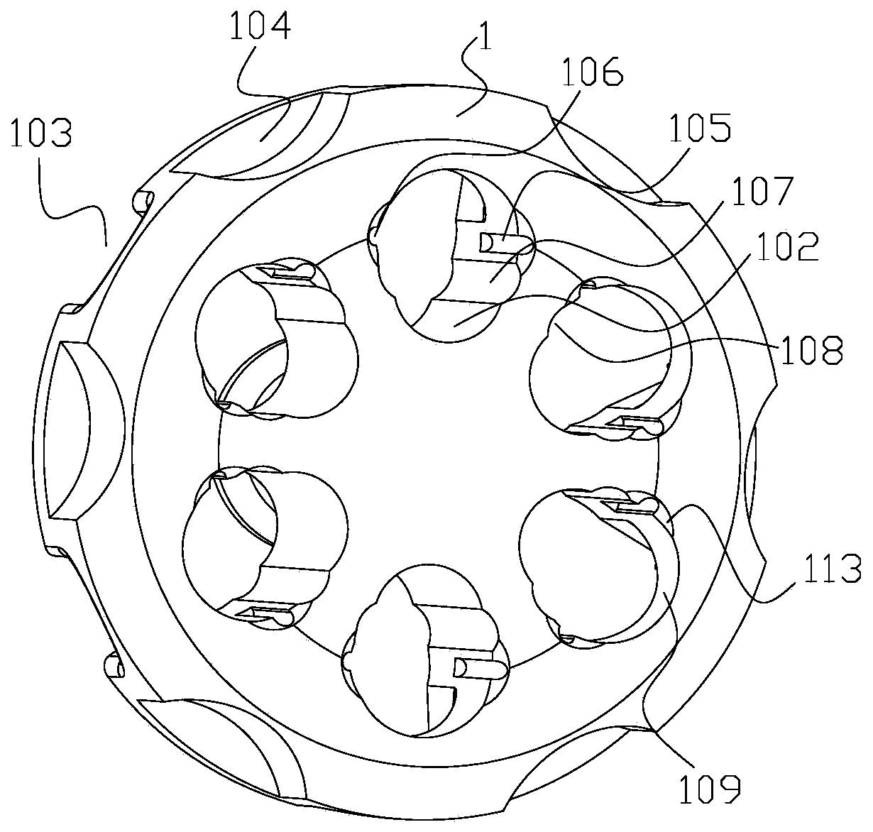
[0025] Such as Figure 1 to Figure 5 Shown, a kind of medical high-speed centrifugal equipment, this equipment comprises a kind of medical high-speed centrifugal rotor. A medical high-speed centrifugal rotor is made of titanium alloy. The rotor includes a centrifugal rotating frame 1 and a hanging cup 2 . The section of the centrifugal rotating frame 1 is T-shaped, and the upper part of the centrifugal rotating frame 1 is in the shape of a round cake. The upper and lower ends of the centrifugal rotating frame 1 are connected with the lower upper end of the centrifugal rotating frame 1 through the transition slope 3 , and the lower part of the centrifugal rotating frame 1 is provided with a shaft matching hole 114 . The top array of the centrifugal rotating frame 1 is provided with a plurality of hanging cup th...


PUM


Abstract

The invention relates to the technical field of medical detection, in particular to medical high-speed centrifuging equipment and a centrifugal rotor. According to the medical high-speed centrifugal rotor, the rotor comprises a centrifugal rotation frame and hanging cups. A plurality of hanging cup grooves are formed in the top face of the centrifugal rotation frame in an array manner, and each hanging cup groove is provided with a matched sliding groove. The positions, corresponding to the hanging cup grooves, on the side wall of the upper portion of the centrifugal rotation frame are provided with U-shaped grooves in an array manner, and openings of the U-shaped grooves are arranged downwards. Each hanging cup comprises a hanging cup pipe and a hanging cup matched connector arranged on the hanging cup pipe, wherein a matched protruding block is arranged at the outer portion of the hanging cup matched connector, and the matched protruding block is matched with the corresponding matched sliding groove and arranged on the centrifugal rotation frame. The medical high-speed centrifuging equipment and the centrifugal rotor have the beneficial effects that hanging cup dismounting and mounting can be convenient, and sampling can be conveniently conducted on multiple sample reagents; all particles in liquid can be prevented from being deposited on the side walls of the hanging cup pipes, and the sampling efficiency and the sampling data accuracy are improved; and the hanging cups are prevented from being in a completely vertical or completely horizontal state, and the centrifugalseparation effect is improved.

Description

technical field [0001] The invention relates to the technical field of medical detection, in particular to a medical high-speed centrifugal device and a centrifugal rotor. Background technique [0002] The main purpose of the medical high-speed centrifuge is to use the high-speed rotation of the centrifuge rotor to generate a strong centrifugal force, speed up the sedimentation speed of the particles in the liquid, and separate the substances with different sedimentation coefficients and buoyant densities in the sample. In a laboratory or a chemical laboratory, the centrifugation method of the test sample commonly used at present is to fix the sampling tube on the rotor of the centrifuge, and centrifuge the liquid sample in the sampling tube through the rotor of the centrifuge running at high speed. However, in the actual operation process, the existing centrifuge rotor has the following technical drawbacks. First, the sampling tube on the existing centrifuge rotor is basica...

Claims


Application Information

Patent Timeline
IPC IPC(8): B04B5/04
Inventor 王加皮孙洋
Owner 王加皮
Why Eureka
Try Eureka