
Processing method for plate type heat pipe

A processing method and plate heat pipe technology, applied in the direction of heat exchange equipment, etc., can solve problems such as the decrease of the uniform temperature capacity of the radiator, the limitation of the heat dissipation capacity of the fins, and the poor heat transfer capacity of the substrate, so as to achieve control of production costs, good heat dissipation effect, easy processing effect

Active Publication Date: 2019-05-31
常州恒创热管理有限公司
View PDF6 Cites 6 Cited by
  • Summary
  • Abstract
  • Description
  • Claims
  • Application Information

AI Technical Summary

Problems solved by technology

However, the current application of fins is limited to the form of mounting on the radiator substrate. When the substrate is a plate heat pipe and the fins are metal fins, the heat dissipation capacity of the fins is limited; and when the substrate is a metal plate, the fins When the sheet is a plate heat pipe, the heat transfer capability of the base plate is poor, and the above two connection structures will lead to a decrease in the uniform temperature capability of the radiator, making the heat dissipation capability poor and unable to meet the heat dissipation requirements.

Method used


Image

  • Processing method for plate type heat pipe
  • Processing method for plate type heat pipe
  • Processing method for plate type heat pipe

Examples


Embodiment 1

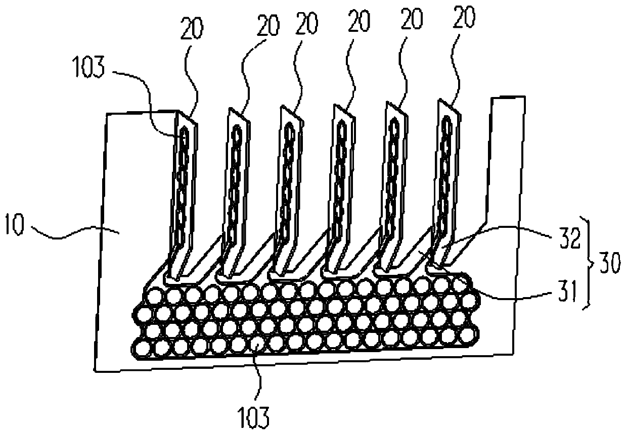
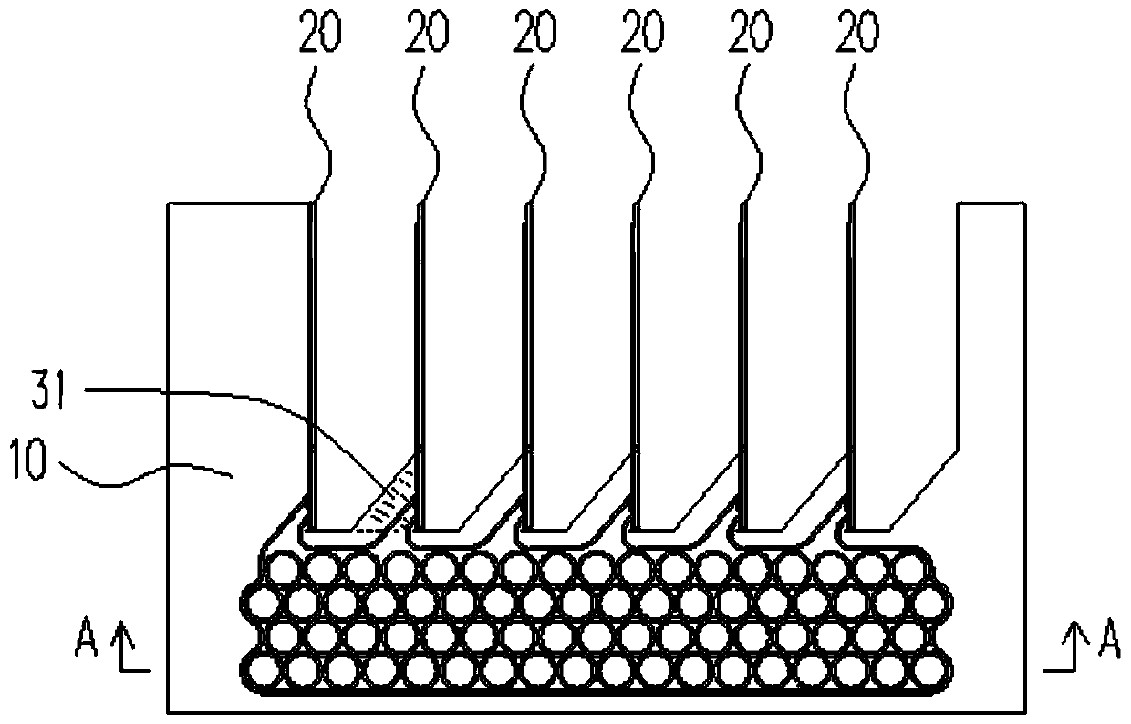
[0047] see Figure 1-Figure 5 , Embodiment 1 of the present invention provides a plate heat pipe for transferring and diffusing heat from a heat source (for example, electronic components or electronic equipment, etc.), the plate heat pipe includes a flat part 10 and a plurality of The fin portion 20, the flat plate portion 10 is provided with a first cavity 101, each fin portion 20 is provided with a second cavity 201, and each second cavity 201 communicates with the first cavity 101, The plate heat pipe is provided with a closed cavity (not shown in the figure), the closed cavity includes a first cavity 101 and a second cavity 201, and the closed cavity is filled with a phase change working medium (not shown in the figure). Shown), the fin portion 20 has a cooling effect. When working, the liquid phase-change working medium in the first cavity 101 absorbs heat from the heat source and vaporizes, and the gaseous phase-change working medium expands rapidly and fills the entir...

Embodiment 2

[0079] see Figure 10 The difference between the plate-type heat pipe provided in Embodiment 2 of the present invention and the plate-type heat pipe in Embodiment 1 is that in this embodiment, the isolated part 103 is omitted, and at this time, the first cavity 101 and the second cavity 102 can also be connected. It is connected, and constitutes a part of the closed cavity, which improves the temperature uniformity of the flat plate part 10 in contact with the heat source and the fin part 20 for heat dissipation, improves the heat dissipation effect, and can meet the heat dissipation requirements of the surface of high-power equipment. Moreover, compared with the first embodiment, the plate heat pipe of this embodiment is easier to process, thereby effectively controlling the production cost.


PUM


Abstract

The invention discloses a processing method for a plate type heat pipe. The processing method comprises the following steps of S20, printing and closing, S30, hot rolling, S60, huffing, S70, cutting,and S90, bending. According to the processing method for the plate type heat pipe, through design of a printing area of rolling resistance agents, as well as the processes of subsequent cutting, bending and the like, the integral forming structure of the plate type heat pipe is achieved, and the heat dissipation effect of the product is good; the operation is simple, and the product is easy to process; and the production cost can be controlled effectively.

Description

technical field [0001] The invention relates to the technical field of heat dissipation, in particular to a processing method of a plate heat pipe. Background technique [0002] With the gradual development of electronic components in the direction of miniaturization, high power, and high performance, the development process will be accompanied by higher heat flux density, and the heat dissipation problem has gradually become a bottleneck restricting the development of highly integrated electronic components. Due to its high thermal conductivity and good temperature uniformity, the plate heat pipe can quickly transfer and diffuse the heat source with high heat density, which meets the requirements of compactness, reliability and flexibility of the heat sink for electronic equipment, and has gradually become a research solution for high-power equipment. Excellent choice for surface cooling problems. [0003] At present, the plate heat pipe has been used to replace the tradit...

Claims


Application Information

Patent Timeline
Patent Type & Authority Applications(China)
IPC IPC(8): B21D53/08
Inventor 黄晓峰上官红玉董爱芳
Owner 常州恒创热管理有限公司
Learn More