Delay automatic closing piece and gas self-closing valve with timing closing function

A gas self-closing valve and automatic closing technology, which is applied in the direction of functional valve types, engine components, valve devices, etc., can solve the problems of increasing input costs and actual installation costs, increasing gas pipeline safety hazards, and electronic devices cannot be directly installed. , to achieve the effect of high practical value, flexible use, and elegant appearance design

Active Publication Date: 2019-05-31
XIAN YOUYI GAS EQUIP
View PDF23 Cites 4 Cited by
  • Summary
  • Abstract
  • Description
  • Claims
  • Application Information

AI Technical Summary

Problems solved by technology

Therefore, in order to realize the timing closing of the self-closing valve, only electronic devices with timing function or delay function can be used. Usually, an electronic shut-off valve with timing function or delay function is installed separately on the gas pipeline, which increases the input cost and actual installation cost, and inevitably adds at least two leaks to the gas pipeline. point, which increases the safety hazard of the gas pipeline; at the same time, since the electronic cut-off valve with timing function or delay function needs to be equipped with a power supply, the power supply needs to be replaced frequently in actual use, otherwise it cannot be used and the operation is inconvenient; and the electronic cut-off valve The sensitivity and effectiveness of the valve are directly affected by the performance of multiple components, so there are problems such as unreliable action and inability to automatically close on time, and the use effect is poor; When the valve is used, it needs to be connected to the power supply, so it is prone to leakage and electric shock problems

Method used


Image

  • Delay automatic closing piece and gas self-closing valve with timing closing function
  • Delay automatic closing piece and gas self-closing valve with timing closing function
  • Delay automatic closing piece and gas self-closing valve with timing closing function

Examples


Embodiment 1

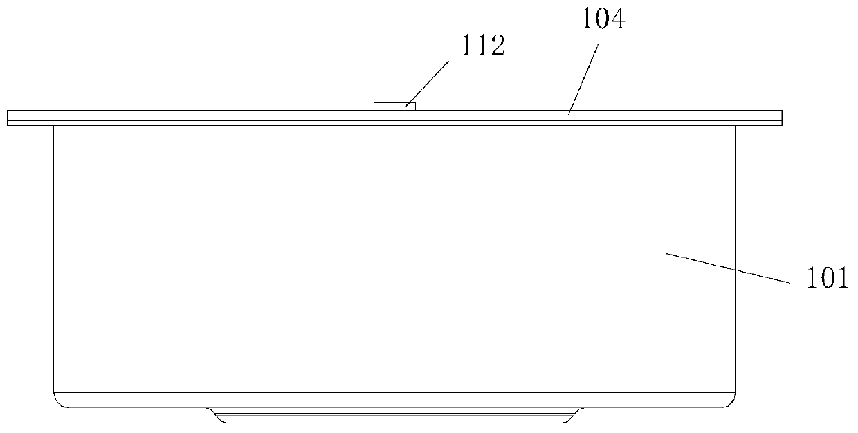
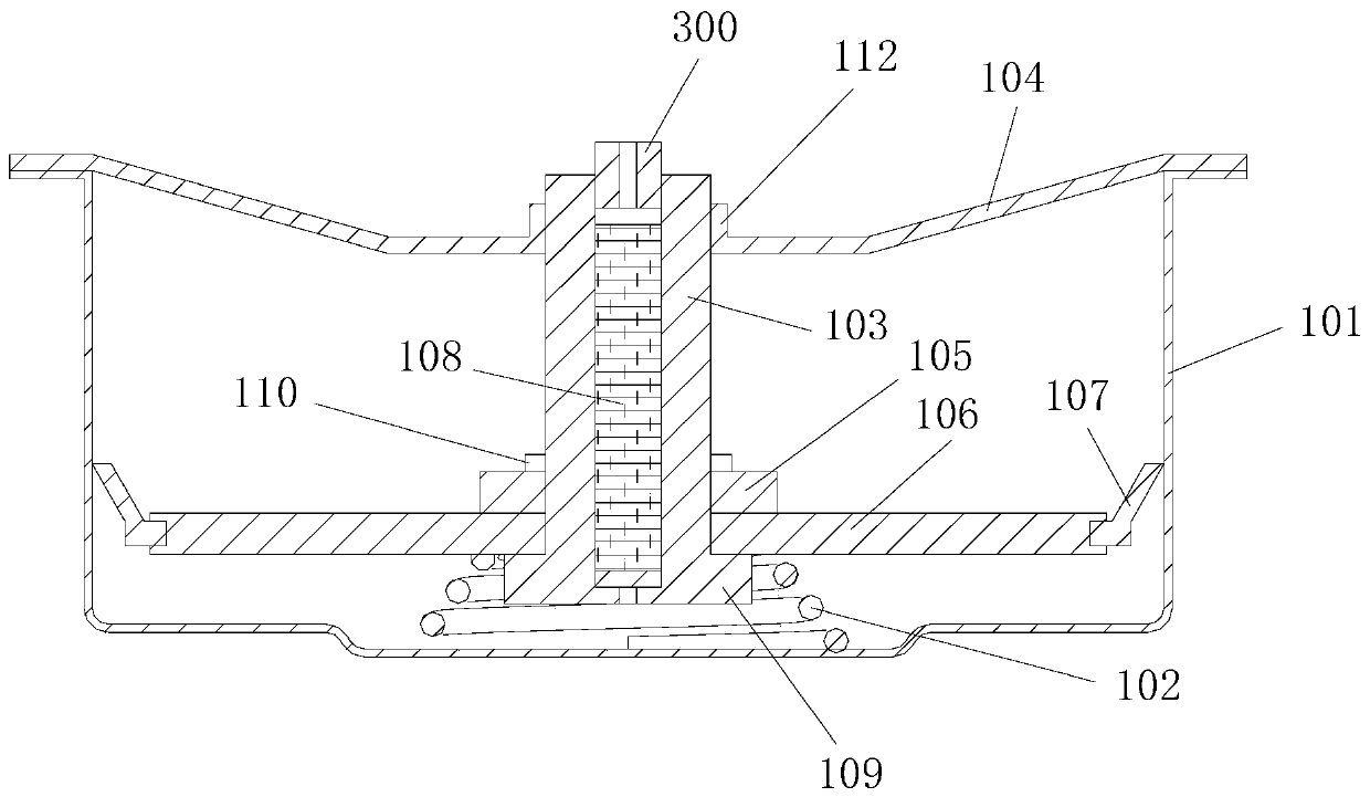
[0090] Such as figure 1 , figure 2 The time-delayed automatic closing member shown includes a casing 101 with an upper opening, a blocking-type moving part arranged in the middle of the inner side of the casing 101 and capable of moving up and down along the central axis of the casing 101, and arranged in the casing 101 and driving The up-moving driving part for the blocking-type moving part to move upward and the compression spring 102 for pushing the blocking-type moving part to move upward along the central axis of the housing 101, the blocking-type moving part, the moving-up driving part Both the member and the compression spring 102 are arranged coaxially with the housing 101.

[0091] The inner cavity of the housing 101 is divided into an upper cavity and a lower cavity directly below the upper cavity by the blocking type moving part, and the blocking type moving part is for the upper part of the lower cavity. A moving part that seals and can move up and down in the c...

Embodiment 2

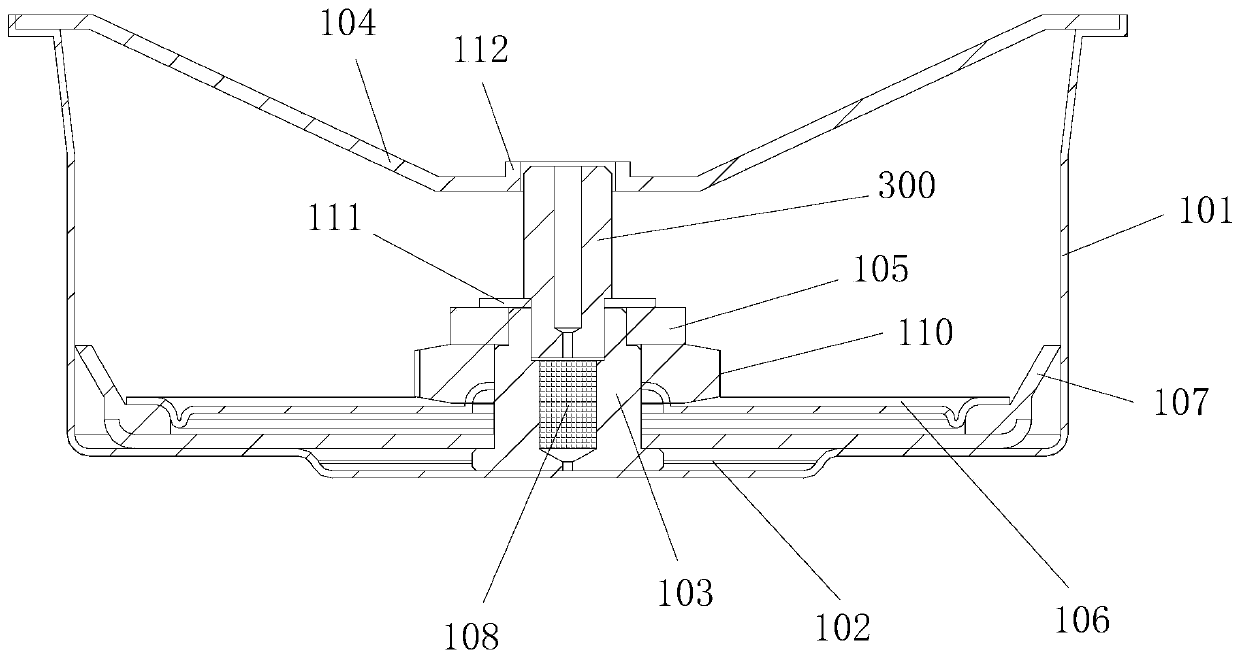
[0150] Such as image 3 As shown, in this embodiment, the difference from Embodiment 1 is: the guide hole for installing the push rod 300 is opened in the middle of the push armature 104; the push rod 300 is coaxially installed in the guide hole.

[0151] The guide sleeve is a guide member for guiding the push rod 300 . The top end of the push rod 300 is located in the guide hole or above the push armature 104 .

[0152] For simple and reliable fixing, the moving plate and the pushing column 103 are locked and fixed by a lock nut 110, and the locking nut 110 is coaxially sleeved on the pushing column 103 and is located above the moving plate;

[0153] The moving plate is fastened and fixed between the locking nut 110 and the limiting ring 109 .

[0154] In this embodiment, the push magnet 105 is located above the locking nut 110;

[0155] The pushing column 103 is provided with an upper limiting member 111 for limiting the pushing magnet 105 , and the upper limiting member ...

Embodiment 3

[0158] Such as Figure 4 A gas self-closing valve with a timing closing function is shown, comprising a self-closing valve body with an air inlet 3 and an air outlet 17, the bottom of the self-closing valve body has a lower opening, and the outer side of the lower opening is The time-delay automatic closing member is installed, and the housing 101 of the time-delay automatic closing member is a blocking member for blocking the lower opening;

[0159] A small film 201 is installed in the valve body of the self-closing valve, a large film 202 is installed on the lower opening, and the small film 201 is positioned above the large film 202; the small film 201 covers the inside of the self-closing valve body The cavity is divided into upper and lower cavities and the upper and lower cavities are respectively the upper valve cavity and the middle valve cavity. The push armature 104 of the delay automatic closing part is located under the large membrane 202 and the cavity between the...


PUM


Abstract

The invention discloses a delay automatic closing piece. The delay automatic closing piece comprises a shell opened at the upper part, a blocked movable piece, an upper moving driving piece arranged in the shell and driving the blocked movable piece to move up, and a compression spring for pushing the blocked movable piece to move up along central axis of the shell; the blocked movable piece, theupper moving driving piece and the compression spring are coaxially arranged with the shell; and the closing piece realize automatic delay closing actions through pushing of the movable piece to moveup through the compression spring under the internal and external pressure difference effect of a blockage piece in the shell, and is low in investment cost and safe and reliable in use process. Meanwhile, the invention further discloses a gas self-closing valve with a timing closing function; the gas self-closing valve comprises a self-closing valve body with an intake port and an exhaust port; alower opening is formed in the bottom of the self-closing valve body; the delay automatic closing piece is mounted on the outer side of the lower opening; and the delay automatic closing piece is mounted at the bottom of the self-closing valve body, so that the self-closing valve achieves the automatic timing closing function under the condition of normal working.

Description

technical field [0001] The invention belongs to the technical field of pipeline gas valves, in particular to a time-delayed automatic closing member and a gas self-closing valve with timing closing function. Background technique [0002] In daily life, there are some potential safety hazards when using household gas pipelines. People often need to close the main gas valve because they often go out, or they forget to close the valve due to negligence when the gas supply of the domestic gas pipeline is suddenly interrupted. It is also easy to cause gas poisoning or cause fires, explosions and other accidents. In the actual use process, it is very important to automatically close the gas self-closing valve in time when the domestic pipeline gas has overpressure, underpressure, hose leakage, hose detachment and gas leakage. One of the indispensable important parts of the machine. [0003] The function of the self-closing valve used today is relatively single. It can only be c...

Claims


Application Information

Patent Timeline
Patent Type & Authority Applications(China)
IPC IPC(8): F16K21/06
Inventor 张成祥张凯
Owner XIAN YOUYI GAS EQUIP
Why Eureka
Try Eureka