Energy-saving environment-friendly commercial stove

An energy-saving, environment-friendly, and commercial technology, which is applied in the direction of household stoves/stoves, household stoves, applications, etc., can solve the problems of low gas utilization rate, improve combustion efficiency, prevent hypoxia or excessive temperature, and improve combustion efficiency

Active Publication Date: 2019-05-31
福建万聚通节能科技股份公司
View PDF12 Cites 3 Cited by
  • Summary
  • Abstract
  • Description
  • Claims
  • Application Information

AI Technical Summary

Problems solved by technology

[0006] Therefore, in view of the above-mentioned problems, the present invention provides an energy-saving and environment-friendly commercial stove, which mainly solves the problem of low gas utilization rate in the prior art

Method used


Image

  • Energy-saving environment-friendly commercial stove
  • Energy-saving environment-friendly commercial stove
  • Energy-saving environment-friendly commercial stove

Examples


Embodiment 1

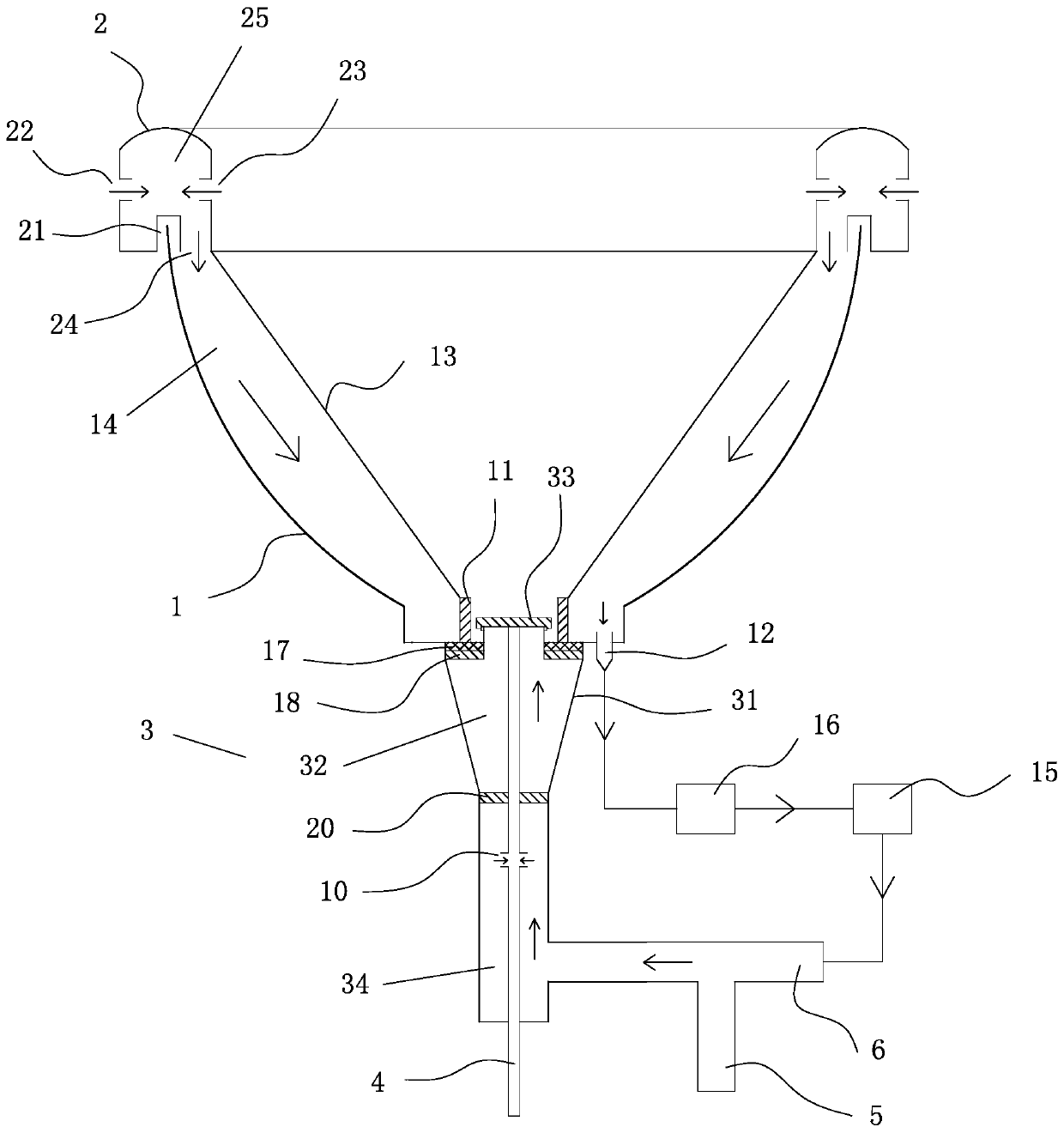
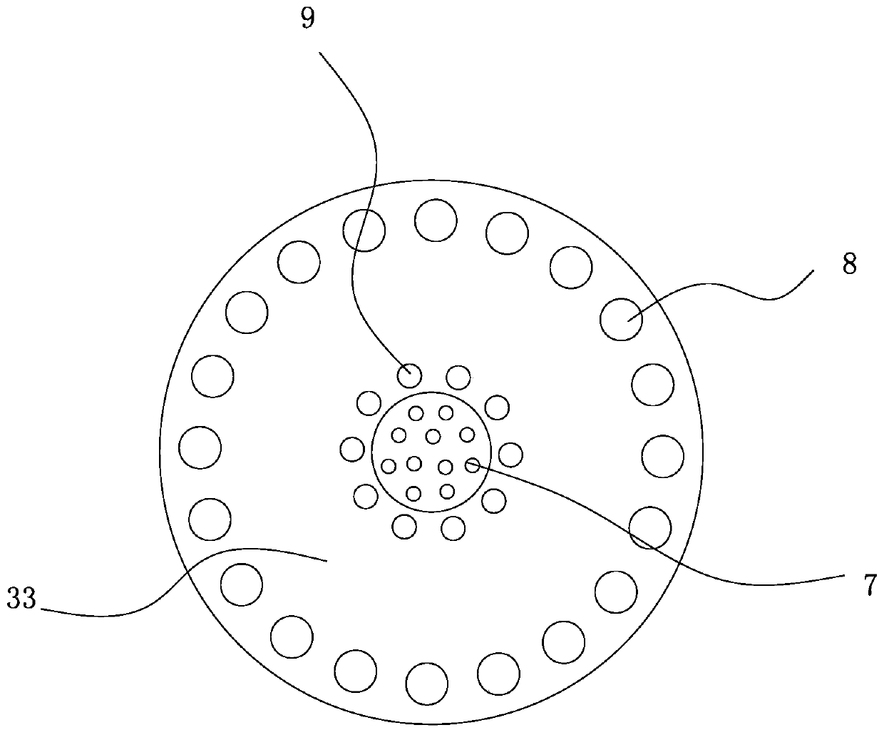
[0024] refer to figure 1 and figure 2, an energy-saving and environment-friendly commercial stove, comprising a furnace 1 with an opening on the upper part, and an annular support frame 2 is arranged on the furnace 1, and the lower part of the support frame 2 has a support groove 21 for supporting the upper end of the furnace 1, A number of first air inlets 22 are evenly arranged around the outer surface of the support frame 2, and an annular air outlet 24 is provided on the lower surface of the support frame 2 inside the furnace 1. An air inlet 22 and a flow channel 25 of the air outlet 24, a plurality of second air inlets 23 are evenly arranged around the inner surface of the support frame 2, and the second air inlet 23 communicates with the flow channel 25, and the furnace 2 The bottom of the bottom is provided with a through hole, and the said through hole is provided with a burner 3, and said burner 3 is respectively provided with a kindling gas inlet pipe 4, a main fir...

Embodiment 2

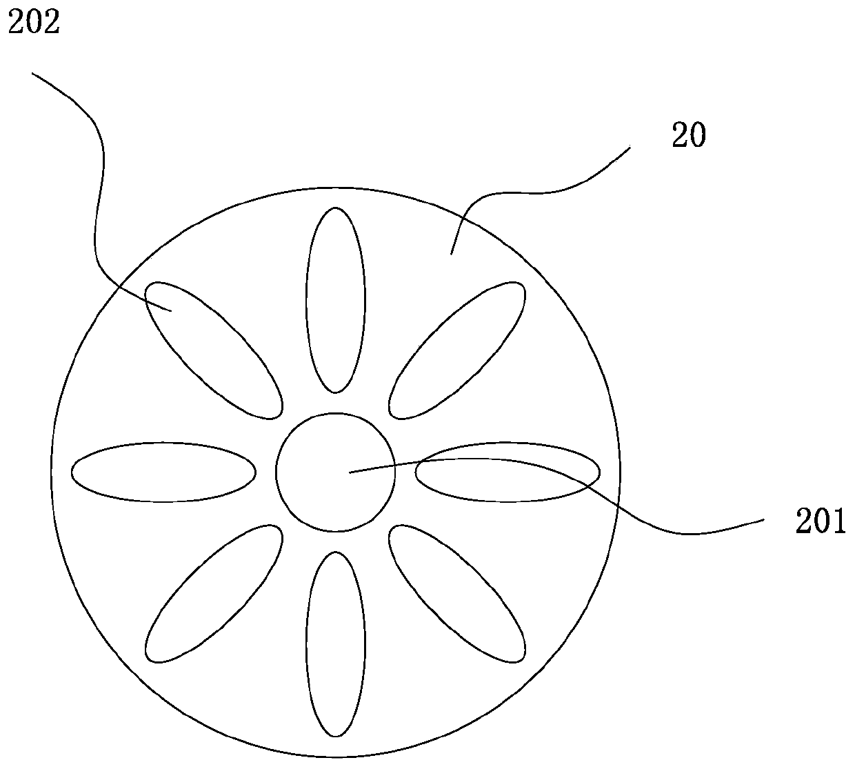
[0034] refer to Figure 4 , an energy-saving and environment-friendly commercial stove, the technical features of which are basically the same as those of Embodiment 1, and the main difference is that a mixing piece 20 is arranged between the mixing chamber 32 and the pre-mixing chamber 34, and the mixing The sheet 20 is a circular sheet-shaped body, and the middle part of the mixing sheet 20 is provided with a circular hole 201 for the ignition inlet pipe 4 to pass through, and the mixing sheet 20 is arranged in a circular matrix with the circular hole 201 as the center. There are eight mixing holes 202 , and each of the mixing holes 202 is an S-shaped structure with a large opening in the middle and gradually decreases toward both ends along the diameter direction of the mixing sheet 20 .

[0035] The working method of the present invention is: the energy-saving and environment-friendly commercial stove, the mixing hole 202 is an S-shaped structure, when the gas passes throu...


PUM


Abstract

The invention relates to an energy-saving environment-friendly commercial stove. The problem that in the prior art, the gas utilization rate is low is mainly solved. The stove comprises a hearth whichis provided with a supporting frame, and the lower portion of the supporting frame is provided with a supporting groove; the outer side surface of the supporting frame is annularly and uniformly provided with first air inlets, and the supporting frame is provided with an annular air outlet; the supporting frame is internally provided with a circulating channel communicating with the first air inlets and the air outlet; the bottom of the hearth is provided with a through hole, ad a combustor is arranged at the through hole and provided with a kindling gas feeding pipe, a main fire gas feedingpipe and an air feeding pipe; a fire collecting ring surrounding the combustor is arranged in the hearth; the bottom of the hearth is provided with an outlet, a fire collecting plate is arranged in the hearth, and the hearth, the supporting frame, the fire collecting plate and the fire collecting ring form a cavity; the air outlet and the outlet both communicate with the cavity; the outlet communicates with the input end of an exhaust fan, the output end of the exhaust fan communicates with the air feeding pipe, and a fireproof explosion-proof device is arranged between the exhaust fan and theair feeding pipe.

Description

technical field [0001] The invention relates to an energy-saving and environment-friendly commercial stove. Background technique [0002] At present, commercial kitchen equipment refers to large-scale kitchen equipment suitable for dining places such as hotels, restaurants, and restaurants, as well as canteens of major institutions, schools, and construction sites. The commercial stoves sold on the market use liquefied gas to burn to form open flame heating, so a large amount of heat energy will be lost during use, or the liquefied gas is not fully burned, resulting in low combustion efficiency of liquefied gas. [0003] Now that non-renewable resources are gradually exhausted, all walks of life are advocating environmental protection and trying their best to save resources. The field of commercial stoves is no exception. The combustion efficiency of liquefied gas is improved by improving the various structures of the stove. For example, the application date: March 16, 200...

Claims


Application Information

Patent Timeline
Patent Type & Authority Applications(China)
IPC IPC(8): F24C3/08F24C15/34F23D14/02F23D14/62
Inventor 林建军
Owner 福建万聚通节能科技股份公司
Why Eureka
Try Eureka