Four-pole armature

An armature and pole electric technology, applied in the field of quadrupole armature, can solve the problems of wear, ablation, affecting the reliability of electromagnetic emission, etc., to reduce the requirements of machining accuracy, improve the contact area and contact efficiency, and reduce the pressure distribution on the contact surface. uniform effect

Inactive Publication Date: 2019-05-31
AIR FORCE UNIV PLA
View PDF5 Cites 4 Cited by
  • Summary
  • Abstract
  • Description
  • Claims
  • Application Information

AI Technical Summary

Problems solved by technology

In the process of electromagnetic emission, the surface where the armature is in contact with the track will be ablated and worn due to the physical effects of high pressure, high temperature, and high speed, which will cause the armature to separate from the track and affect the reliability of electromagnetic emission.

Method used


Image

  • Four-pole armature
  • Four-pole armature
  • Four-pole armature

Examples


Embodiment 1

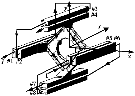
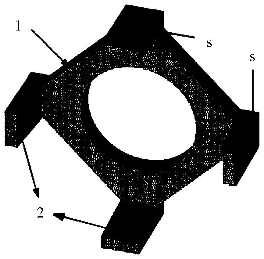
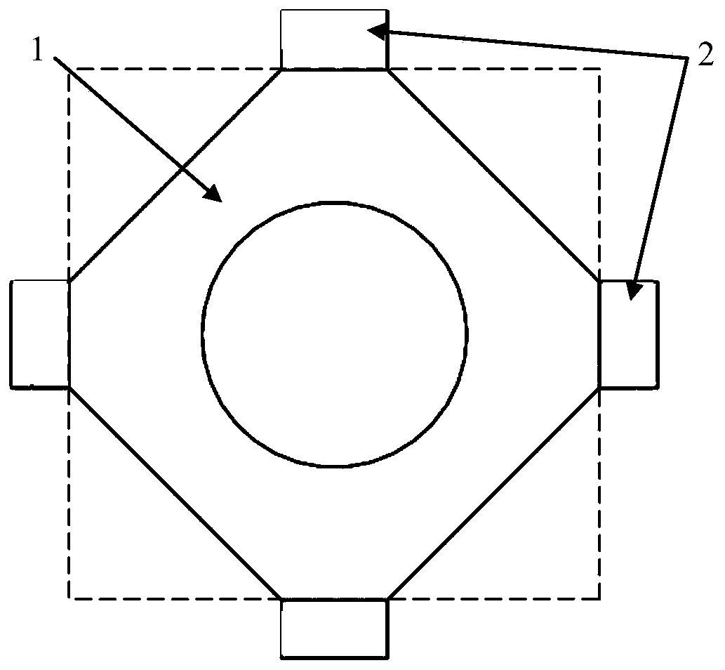
[0044] Such as figure 1 , figure 2 , image 3 and Figure 4 As shown, the armature of this embodiment includes an armature body 1 and an armature cantilever 2 connected to the armature body 1 . The armature body 1 is an octagonal block, and a through hole (not labeled) is arranged in the center of the armature body 1 . The armature cantilever 2 is a flexible arm, and the four armature cantilever 2 are respectively connected to two opposite sides of the armature body 1. The armature cantilever 2 moves from the front end of the armature body 1 along the extending backwards in a parallel direction. For ease of description, the end of the armature cantilever 2 connected to the armature body 1 is defined as the head, then the free end of the armature cantilever 2 is the tail, and the head of the armature cantilever 2 is connected to the front end of the armature body 1. flush. The armature cantilever 2 has a contact surface s that is in sliding contact with the track in the ...

Embodiment 2

[0049] Figure 8 , Figure 9 , Figure 10 and Figure 11 It is a schematic structural diagram of the armature cantilever according to Embodiment 2 of the present invention. The difference between this embodiment and Embodiment 1 is: the contact surface s where the armature cantilever 2 contacts the track is a curved surface, that is, the outline of the contact surface s is curved, and the front end point of the curve is between the axis of the armature body 1. The difference between the distance between the curve and the distance between the end point of the curve and the axis of the armature body 1 is the interference amount t of the armature cantilever r (the contact surface is an inclined plane in embodiment 1, then the profile of the contact surface is linear, and the amount of interference t r is the difference between the distance between the front end point of the straight line and the axis of the armature body 1 and the distance between the end point of the straigh...


PUM


Abstract

The invention relates to a four-pole armature. The four-pole armature comprises an armature body and armature cantilevers. The armature body is a block body of which the cross section is shaped like acentrally symmetrical octagon. The armature cantilevers are connected with the armature body and are connected to four opposite lateral sides of the armature body, wherein two of the four lateral sides are opposite to the other two lateral sides correspondingly. The length of the lateral sides is the same as the width of the armature cantilevers. The armature cantilevers are flexible arms and extend backwards in the direction parallel to the armature moving direction from the armature body. The tail portions of the armature cantilevers are closer to the axis of the armature body than the headportions of the armature cantilevers. The armature cantilevers are in interference fit with a track in an electromagnetic emitter. The armature cantilevers extending outwards from the armature body are arranged, and the flexible armature cantilevers are in interference fit with the track, so that sufficient contact area and contact pressure between the armature and the track can be obtained whenthe armature is installed, the problems that the armature and the track are separated due to phenomena like abrasion and ablation of the contact surface between the armature and the track in the electromagnetic emission process are solved, and the stability of electromagnetic emission is ensured.

Description

technical field [0001] The invention belongs to the technical field of ground-to-air missile electromagnetic ejection, in particular to a quadrupole armature used for a quadrupole electromagnetic launcher. Background technique [0002] Electromagnetic launch is a new-concept military technology that breaks through traditional missile and artillery launch principles. It is currently a key technology being vigorously developed by all military powers in the world. Applying electromagnetic launch technology to surface-to-air missile weapon systems can lay a theoretical foundation for the unification of active and under-research air defense missile catapults, the development of a general launch platform, and the construction of a family of air defense and anti-missile equipment, so as to maximize the use of various combat effectiveness of missiles. [0003] The current electromagnetic launcher mainly includes a track and an armature. The armature is in contact with the track and...

Claims


Application Information

Patent Timeline
Patent Type & Authority Applications(China)
IPC IPC(8): F41B6/00
Inventor 刘少伟苗海玉关娇时建明陆心平边友
Owner AIR FORCE UNIV PLA
Why Eureka
Try Eureka