Pipeline deformation monitoring method and system

A technology for deformation monitoring and pipelines, which is applied in pipeline systems, measuring devices, gas/liquid distribution and storage, etc., can solve the problems of inability to realize distributed monitoring, expensive maintenance costs, narrow application range, etc., and achieve good event recognition effect, Effects with fast processing speed and simple structure

Active Publication Date: 2019-05-31
广东聚源管业实业有限公司
View PDF8 Cites 9 Cited by
  • Summary
  • Abstract
  • Description
  • Claims
  • Application Information

AI Technical Summary

Problems solved by technology

The negative pressure wave method has the advantages of low cost and mature technology, but the negative pressure wave method is mostly used in short-distance straight oil pipelines, with a narrow application range and low positioning accuracy; the acoustic wave method has the advantages of high positioning accuracy, but because the sensor is a discrete Installation, so distributed monitoring cannot be achieved, and the later maintenance costs are expensive

Method used


Image

  • Pipeline deformation monitoring method and system
  • Pipeline deformation monitoring method and system
  • Pipeline deformation monitoring method and system

Examples


Embodiment 1

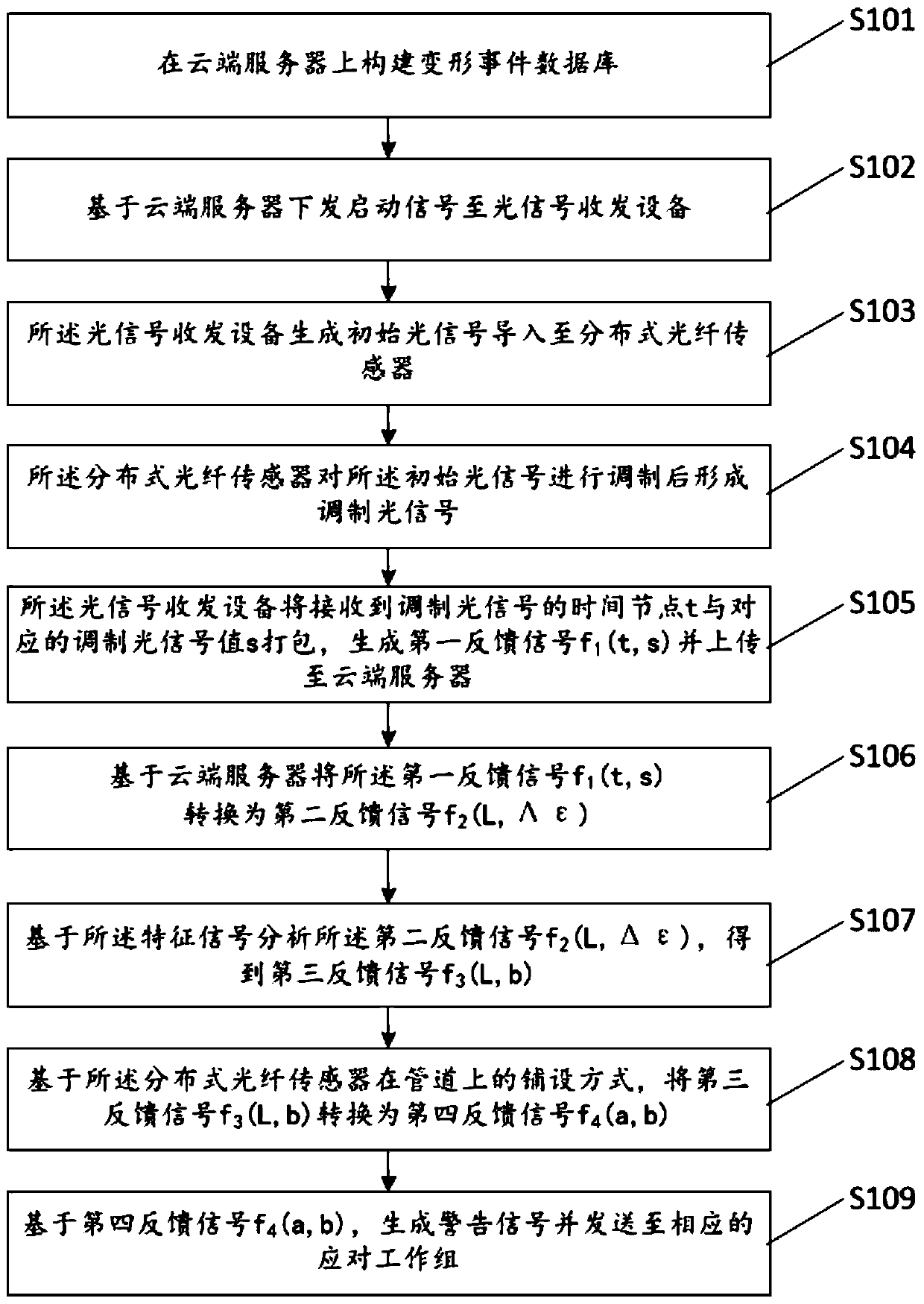
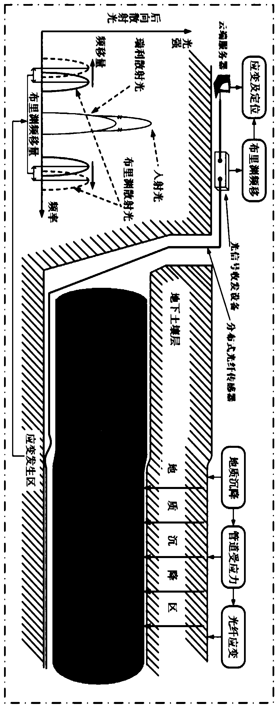
[0068] The instantaneous characteristic signal of a single distributed optical fiber sensor is mainly used for analysis and comparison with the data of the distributed optical fiber sensor acquired in an information collection; the distributed optical fiber sensor data acquired in an information acquisition is the distance-new variable ( L-Δε) relationship curve, using the instantaneous characteristic signal of a single distributed optical fiber sensor, through the analysis of the L-Δε curve, it can be analyzed whether the distributed optical fiber sensor is deformed along the length direction, and what is the deformation value.

Embodiment 2

[0070] The deformation of the pipeline is mainly driven by stress. The instantaneous characteristic signal of a single distributed optical fiber sensor can only analyze whether the pipeline is deformed at a certain moment; Performance, such as the road above the pipeline, when heavy trucks pass by, the stress on the pipeline increases and the degree of deformation increases, but the stress returns to normal in a short time; the above process will not affect the performance of the pipeline itself, but this process can only be achieved through continuous Therefore, such events need to be compared with the continuous characteristic signals of a single distributed fiber optic sensor.

Embodiment 1

[0072] In embodiment 1, a single distributed optical fiber sensor is used to realize the function of locating the location of the deformation event in the length direction of the pipeline; specifically, the pipeline is a three-dimensional structure, and the deformation of the pipeline is not a protrusion or depression at a certain position, but The entire length of the pipe will be deformed. By laying multiple distributed optical fiber sensors on the pipeline, the specific deformation direction of the pipeline can be analyzed. Through the confirmation of the direction of pipeline deformation, the cause and hazard of pipeline deformation can be further deduced, which can be used as a reference for the design of the solution. For such events, it is reasonable to analyze and compare the instantaneous characteristic signals of multiple distributed optical fiber sensors.


PUM


Abstract

The invention provides a pipeline deformation monitoring method and system. The system comprises a cloud server, an optical signal transmit-receive device, and a distributed optical fiber sensor. According to the pipeline deformation monitoring method, an event database is set, so that a deformation event can be accurately identified; sequence identification codes are set, so that modulated optical signals measured at different time points can be identified; and a d-t database and the like are set, so that the data processing speed of the cloud server can be increased, and high processing speed and a good event identification effect can be realized. The optical signal transmit-receive device of the system is simple in structure, low in production and maintenance cost, can be favorably popularized and applied on a large scale, and has high practicality in actual use.

Description

technical field [0001] The invention relates to the field of distributed optical fiber sensing, in particular to a pipeline deformation monitoring method and system. Background technique [0002] The large-scale oil and gas pipelines buried deep underground will be deformed due to stress hazards caused by geological subsidence, and then there will be problems such as pipeline damage and leakage. Once a problem occurs, it will cause damage to the surrounding ecological environment, and in severe cases, it will cause an explosion, threatening the safety of people's lives and property. [0003] At present, the widely used oil and gas pipeline leakage monitoring technologies mainly include negative pressure wave method, acoustic wave method and so on. The negative pressure wave method has the advantages of low cost and mature technology, but the negative pressure wave method is mostly used in short-distance straight oil pipelines, with a narrow application range and low positio...

Claims


Application Information

Patent Timeline
Patent Type & Authority Applications(China)
IPC IPC(8): G01B11/16F17D5/00G06F16/215
Inventor 汤铁卉钟锋
Owner 广东聚源管业实业有限公司
Why Eureka
Try Eureka