Rotor fulcrum load identification experimental device and method based on retainer spring squirrel cage strain

An identification experiment and squirrel cage technology, applied in the field of gas turbine engines, can solve the problems of inaccurate test results and test limitations, and achieve the effect of simple structure and accurate identification test results.

Active Publication Date: 2019-05-31
DALIAN JIAOTONG UNIVERSITY
View PDF5 Cites 6 Cited by
  • Summary
  • Abstract
  • Description
  • Claims
  • Application Information

AI Technical Summary

Problems solved by technology

At present, although there are some literatures and patents aiming at the vibration research of the elastic support-rotor system, strain gauges are used to study the strain or vibration of the elastic squirrel cage structure, such as papers: High cycle fatigue test of series squirrel cage elastic support (Yang Zhengbing), squirrel cage elastic Supporting structure parameter optimization design and test (Feng Guoquan) and patent: elastic supporter vibration strain monitoring method (201410282663.7), etc., but most of them focus on radial load or vibration. It also bears axial loads such as bearing axial preload, blade excitation axial thrust load, and axial alternating force generated by the turntable bias, so only radial load or vibration research is carried out. On the one hand, a single radial The load test includes the effect and influence of the axial load, and the test results are inaccurate. On the other hand, the pure radial load test will also make the test more limited, making it difficult to find and reveal problems in the axial load or vibration of the rotor system, such as blades Changes in airflow alternating force, axial alternating force generated by turntable bias gyro torque, etc.

Method used


Image

  • Rotor fulcrum load identification experimental device and method based on retainer spring squirrel cage strain
  • Rotor fulcrum load identification experimental device and method based on retainer spring squirrel cage strain
  • Rotor fulcrum load identification experimental device and method based on retainer spring squirrel cage strain

Examples


Embodiment Construction

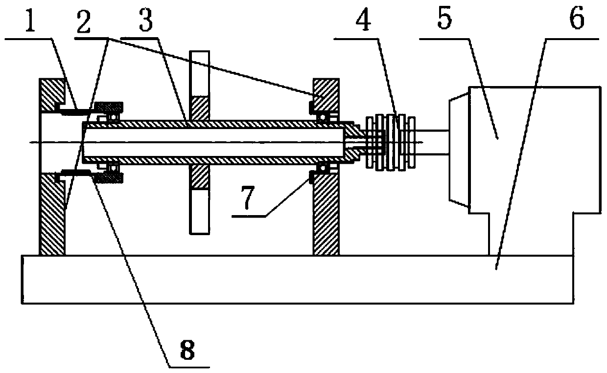
[0029] The structure of the test device of the rotor fulcrum load identification method based on the elastic squirrel cage strain of the present invention is as follows: figure 1 As shown, it includes a squirrel cage force testing device 1 , a fulcrum 2 , a turntable shaft 3 , a coupling 4 , a driving motor 5 , a base 6 and an axial pretensioning device 7 . The squirrel cage force testing device 1 is installed on the squirrel cage, and is used to test the load size in each direction under the action of compound load. The test device has at least a squirrel cage and its squirrel cage force testing device 1; the middle part of the support 2 used as a fulcrum has a through hole and The elastic squirrel cages 8 are connected and supported by rolling bearings. The lower part of the support 2 is fixedly connected with the base 6 through bolts; there are at least two supports 2, and the two supports 2 are connected with the turntable shaft 3 through rolling bearings to support the rot...


PUM


Abstract

The present invention provides a rotor fulcrum load identification experimental device and method based on a retainer spring squirrel cage strain. The device comprises a squirrel cage test device, fulcrums, a turntable shaft, a coupler, a drive motor, a base, and an axial pretensioning device. The load identification method comprises the following steps of: sensitivity analysis of a squirrel cageunder combined load conditions; arrangement of a squirrel cage test device sensor; force parameter static calibration; and force parameter dynamic identification. The rotor fulcrum load identificationexperimental device and method achieve the composite load test and identification of the radial and axial loads of the retainer spring-rotor system fulcrum, employ a decoupling decomposition method to avoid radial and axial load coupling influences, and the identification test result is more accurate; the test device is simple in structure to simulate the experiments in complex working conditionssuch as the bearing pretensioning state, the unbalance rotor, the blade axial push load and fulcrum misalignment so as to provide technical support for the gas turbine engine rotor system fulcrum load change research in the complex working conditions.

Description

technical field [0001] The invention relates to the field of gas turbine engines in rotating machinery. Background technique [0002] The working conditions of the rotor system of gas turbine engines such as aeroengines are extremely complex, such as blade rubbing, flying loss, over-critical rotor system, unbalance, and alternating axial load caused by air flow will cause load changes at the fulcrum of the rotor system , only by accurately obtaining the fulcrum load of the rotor system can the strength analysis of the spring squirrel cage and rotor vibration control be effective. Therefore, the identification of the fulcrum load of the rotor system is of great significance for the research of the rotor system of gas turbine engines such as aeroengines. [0003] The rotor system of an aero-engine generally adopts an elastic support structure (hereinafter referred to as an elastic support structure, such as a squirrel-cage structure), which is used to comprehensively adjust th...

Claims


Application Information

Patent Timeline
Patent Type & Authority Applications(China)
IPC IPC(8): G01M13/027
Inventor 王美令温保岗韩清凯
Owner DALIAN JIAOTONG UNIVERSITY
Why Eureka
Try Eureka