Eureka AIR delivers breakthrough ideas for toughest innovation challenges, trusted by R&D personnel around the world.

Constant current-constant voltage secondary automatic switching circuit and resonant wireless electric energy transmission system

A technology of automatic switching and switching circuits, which is applied in the direction of circuit devices, battery circuit devices, collectors, etc., can solve the problems of reducing system stability and increasing system complexity, and achieves reducing stability, good characteristics, and high system conversion efficiency Effect

Inactive Publication Date: 2019-05-31
JIANGSU UNIV
View PDF6 Cites 10 Cited by
  • Summary
  • Abstract
  • Description
  • Claims
  • Application Information

AI Technical Summary

Problems solved by technology

However, no matter what method is used to achieve constant current or constant voltage output, it involves the communication between the primary side and the secondary side. In the high-frequency and high-magnetic environment, the addition of communication modules increases the complexity of the system to a certain extent. Reduced system stability

Method used


Image

  • Constant current-constant voltage secondary automatic switching circuit and resonant wireless electric energy transmission system
  • Constant current-constant voltage secondary automatic switching circuit and resonant wireless electric energy transmission system
  • Constant current-constant voltage secondary automatic switching circuit and resonant wireless electric energy transmission system

Examples


Embodiment Construction

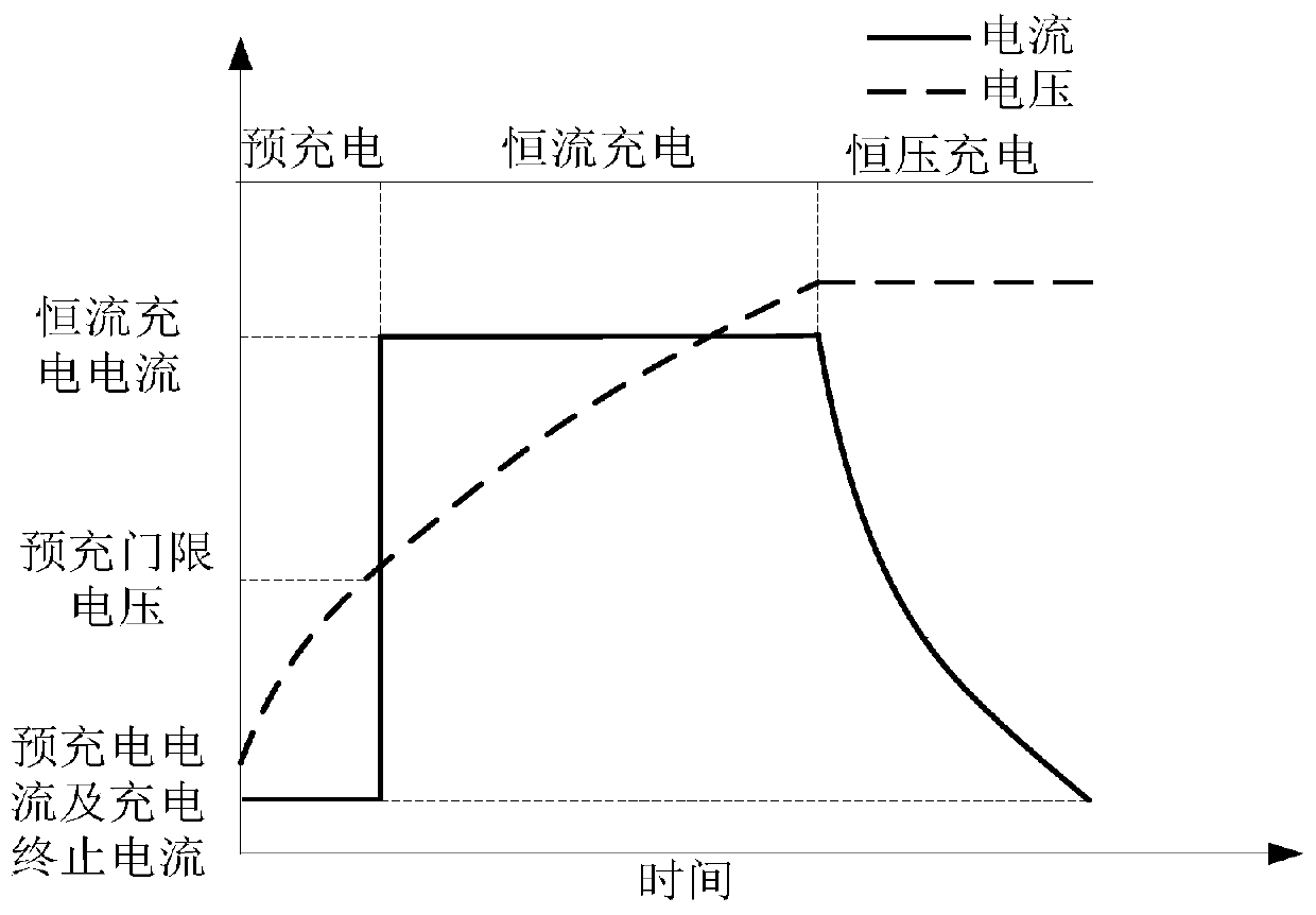
[0028] In order to make the method, purpose and advantages of the present invention clearer, it will now be described in detail in conjunction with the accompanying drawings. figure 1 It can be seen that the corresponding change trend of each parameter in the battery charging process, in the battery charging process mainly includes three stages and pre-charging stage, constant current charging stage, constant voltage charging stage. The charging current in the pre-charging stage is small and mainly serves the purpose of protecting the battery. However, in most cases, the cycle charging of the battery does not involve this stage. With the progress of the pre-charging process, the voltage of the battery is increased. When the voltage When the pre-charge threshold is reached, the charging process of the battery will switch to the constant current charging stage, through which the purpose of fast charging can be achieved. When the electric energy reaches a specific state, the batt...


PUM


Abstract

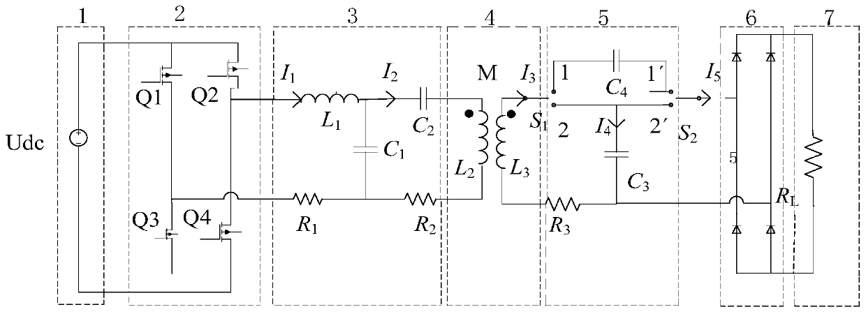
The invention discloses a constant current-constant voltage secondary automatic switching circuit and a resonant wireless electric energy transmission system. The system can switch different chargingmodes according to the charging state of a battery so as to achieve constant current or constant voltage output of the system. Usually, in the initial stage of battery charging, the system carries outcharging through a constant current mode to achieve fast charging, and in the end of charging, in order to protect a circuit, charging is performed in a constant voltage mode. Compared with existingwireless electric energy transmission constant voltage or constant current output, by using a compensation topology structure of the invention, communication between a primary side and a secondary side is avoided and a control aspect is simplified, and the stability and the safety of the wireless electric energy transmission system are improved. On a structure aspect, compared with an existing compensation topology, the compensation topology of the invention can be used to reduce reactive power and transmission efficiency is greatly increased. Through the switching of the two compensation topologies, the limitation of single compensation topology output is overcome and the suitable range of wireless electric energy transmission is extended.

Description

technical field [0001] The invention belongs to the technical field of wireless power transmission, and specifically relates to a constant current-constant voltage secondary side automatic switching circuit and a new type of wireless power transmission system based on magnetic coupling resonance, which can achieve different compensation topology structures by changing the secondary side characteristic output. Background technique [0002] In recent years, with the development of society, the transmission of electric energy plays a pivotal role in economic development. Compared with traditional power transmission methods, wireless power transmission technology can not only get rid of the shackles of wires, but also the transmission process is more convenient and safe. Therefore, It has received extensive attention in recent years. Compared with other wireless power transfer technologies (inductive wireless power transfer, laser wireless power transfer, and microwave radiatio...

Claims


Application Information

Patent Timeline
Patent Type & Authority Applications(China)
IPC IPC(8): H02J7/02H02J50/12H02J5/00
Inventor 闫小喜赵振洲尹亚东陈雪松
Owner JIANGSU UNIV
Why Eureka
Eureka Blog
Learn More