Check patentability & draft patents in minutes with Patsnap Eureka AI!

Casting technology of buffer box body

A buffer box and process technology, which is applied in the field of technology, can solve the problems of not very ideal fixing effect of the formwork, poor heat transfer speed, and decreased impact resistance of the box, so as to achieve a compact and compact box. The effect of enrichment and improvement of product pass rate

Pending Publication Date: 2019-06-04
唐山市鑫彬铁路配件厂
View PDF5 Cites 0 Cited by
  • Summary
  • Abstract
  • Description
  • Claims
  • Application Information

AI Technical Summary

Problems solved by technology

However, there is a gap between the iron sands, which makes the heat conduction speed slow, which is not very consistent with the heat transfer speed required for the solidification of molten steel. At the same time, there is a certain extrusion gap between the iron sands, which is not ideal for fixing the mold shell.
At the same time, in the transverse cutting and dissection of the box body, it is found that on the side wall of the box body, especially on the raised ribs, air holes occasionally appear. As a result, the existence of such bubbles destroys the compactness of the internal structure as a whole, greatly reduces the impact resistance of the box, and makes such a box a substandard product

Method used


Image

  • Casting technology of buffer box body
  • Casting technology of buffer box body
  • Casting technology of buffer box body

Examples


Embodiment Construction

[0025] Below in conjunction with accompanying drawing, the present invention will be further described by preferred embodiment:

[0026] Such as figure 1 As shown, the casting process of the buffer box includes the following steps:

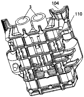
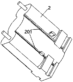
[0027] (a) First, use zircon sand coated sand as the material to make the casting mold for the buffer box. The casting mold includes a mold shell and an inner core 2. The mold shell has a cavity 101, and casting pipes 102 are respectively provided on both sides of the cavity 101. And the overflow pipe 103, the casting pipe 102 and the overflow pipe 103 are all connected with the cavity 101, and the top of the cavity 101 is provided with a liquid replenishment port 3, and the lower port 350 of the liquid replenishment port 3 is connected with the cavity 101, and the inner core 2 is provided with There are vertical grooves 201, and the vertical grooves 201 are used to shape the reinforcing ribs of the side walls of the box after the mold cavity is ...


PUM


Abstract

The invention discloses a casting technology of a buffer box body. The casting technology of the buffer box body comprises the following steps that (a) a casting mold is manufactured by using zircon sand precoated sand, the casting mold comprises a mold shell and an inner core, a cavity is formed in the mold shell, a casting pipeline and an overflow pipeline are correspondingly arranged on the twosides of the cavity, and the casting pipeline and the overflow pipeline both communicate with the cavity, liquid supplementation openings are formed in the top of the cavity, the liquid supplementation openings communicate with the cavity, and vertical grooves are formed in the inner core; (b) the inner core is placed in the mold shell and is fixed; (c) liquid steel is poured into a casting opening of the casting pipeline until a mold cavity is filled with the liquid steel and the overflow pipeline and the liquid supplementation openings are filled with the liquid steel; (d) after the liquidsteel is subjected to cooling solidification, steel plates are opened and the mold shell and the inner core are disassembled, an initial buffer box body is obtained; and (e) unnecessary parts of the initial buffer box body are cut off, and the initial buffer box body is polished to obtain the buffer box body. The improvement of the casting mold by the technology is beneficial to avoiding the formation of bubbles and can significantly improve the qualified rate of products.

Description

technical field [0001] The invention relates to a process, in particular to a process for casting a buffer box body. Background technique [0002] The buffer is an important part of the coupler buffer device of railway freight cars. Its function is to ease the longitudinal impulse generated during the running of the train, absorb the impact energy, improve the stability of the running of the freight car, and avoid damage to the vehicle and goods. The existing dry friction buffer, such as the MT-2 type buffer, is composed of a box body, a friction system and a spring system. Ribs are used to enhance the mechanical strength of the box itself, and the buffer box is an important part that carries the friction system and spring system and withstands the impact force. Invention patent application CN104525870 A discloses a manufacturing method of a buffer box. First, a mold shell and an inner core are made. The inner core is placed in the mold shell and a cavity is left between th...

Claims


Application Information

Patent Timeline
IPC IPC(8): B22C9/02B22C9/08B22C9/24B22C15/24
Inventor 董赞杰
Owner 唐山市鑫彬铁路配件厂
Features
  • R&D
  • Intellectual Property
  • Life Sciences
  • Materials
  • Tech Scout
  • Unparalleled Data Quality
  • Higher Quality Content
  • 60% Fewer Hallucinations
Learn More