
Sealing device for guide groove of sealing-tape machine

A technology of sealing device and material guide groove, which is applied in the direction of transportation, packaging, loading/unloading, etc., can solve the problems affecting the health of on-site operators, time-consuming and laborious replacement of side sealing plates, frequent replacement of sealing bead, etc., and achieves a simple connection method Moreover, the replacement is convenient and quick, and the effect of solving the problem of dust pollution

Pending Publication Date: 2019-06-04
MCC NORTH (DALIAN) ENG TECH CO LTD
View PDF1 Cites 0 Cited by
  • Summary
  • Abstract
  • Description
  • Claims
  • Application Information

AI Technical Summary

Problems solved by technology

[0003] There are the following problems in the currently used material guide trough: 1) There is a clearance fit between the material guide trough and the upward belt of the tape machine, and the tape machine is easy to trap material, resulting in scratches and damage to the upward belt, and the dustproof effect is not good. Good; 2) Install the sealing bead on the side plate and the rear baffle of the material guide chute, which is vertically attached to the upward belt. The initial sealing effect is good, but the sealing bead is easy to wear. The dust is serious and the environment is extremely poor, which seriously affects the health of on-site operators; 3) The sealing bead is replaced frequently, and it is not easy to operate when replacing
"The side sealing device of this invention patent is installed on the inner side of the lower part of the material guide trough, and is inside the material guide trough. Since the side sealing plate is easy to wear and needs to be replaced frequently, there is a problem that the replacement of the side sealing plate is time-consuming, laborious and difficult to operate.

Method used


Image

  • Sealing device for guide groove of sealing-tape machine
  • Sealing device for guide groove of sealing-tape machine
  • Sealing device for guide groove of sealing-tape machine

Examples


Embodiment Construction

[0021] The present invention will be further described below in conjunction with accompanying drawing.

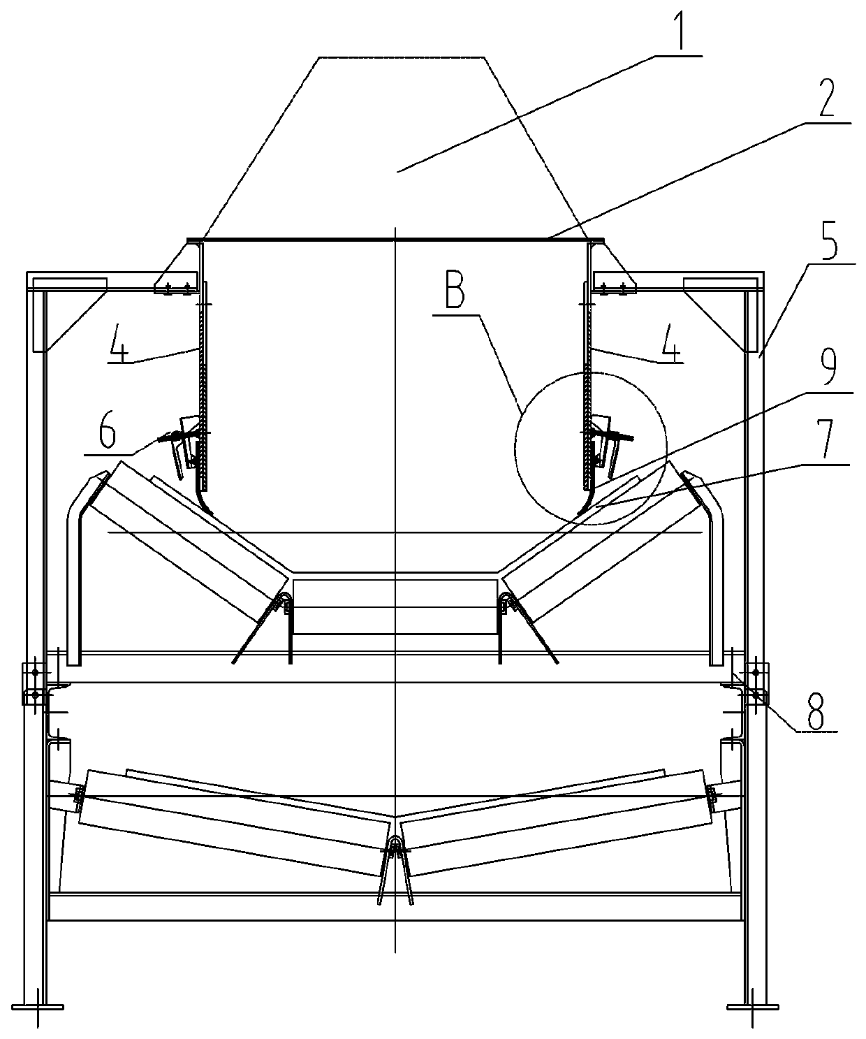
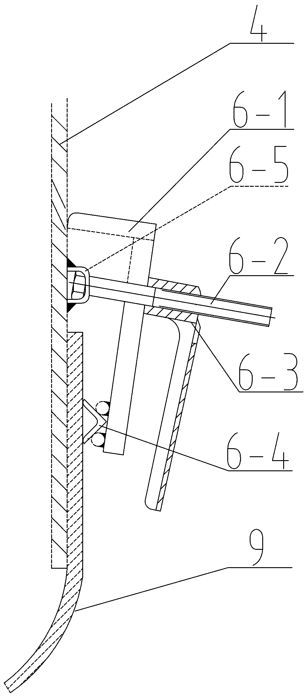
[0022] Such as Figure 1-Figure 3 As shown, a kind of sealing device used for the guide groove of the belt conveyor of the present invention includes: a guide plate 2 communicated with the funnel 1, two guide groove side plates 4, a rear baffle plate 3 and a front curtain. Feed trough, the belt conveyor located below the material guide trough and the sealing and dust-proof device respectively arranged between the two material guide trough side plates 4 and the tailgate 3 and the belt conveyor, the described material guide trough is an upper closed trough body, the guide groove is installed on the middle frame 8 of the tape machine through the bracket 5, and it is characterized in that: the sealing and dustproof device is composed of a locking assembly 6 and a rubber sealing swash plate 9,

[0023] The locking assembly includes a bolt rod 6-2, an L-shaped pressing plate 6-1...


PUM


Abstract

The invention relates to a sealing device for a guide groove of a sealing-tape machine. The sealing device comprises the guide groove, the sealing-tape machine and a sealing device body. The sealing device is characterized in that the sealing device body is composed of a locking assembly and a sealing inclined plate, the locking assembly composes a bolt rod, a pressing plate, a nut and a steel angle used for compressing and fixing the sealing inclined plate, one end of the bolt rod is hinged to the outer side of the lower part of a side plate of the guide groove, the pressing plate is slidablyconnected to the middle part of the bolt rod in a sleeving mode, the nut is connected to the other end of the bolt rod in a threaded and sleeving mode, two limiting baffle blocks are arranged on theend part of the long edge of the pressing plate, and the right-angle end of the steel angle is compressed and fixed between the two limiting baffle blocks; and the upper end of the sealing inclined plate is attached to the outer side of the lower part of the side plate of the guide plate in parallel and compressed and fixed by the steel angle, and the lower end of the sealing inclined plate is inserted between the lower end of the side plate of the guide groove and an upgoing belt of the sealing-tape machine and in surface contact with the surface of the upgoing belt. The sealing device has the advantages that the surface contact sealing is good in effect, and the problems of dust and scattering are solved; the manufacturing is simple, and the cost is low; and the pressing and connecting method is simple and firm, the maintenance and replacement is convenient and quick, time and labor are saved, and safety and high efficiency are achieved.

Description

technical field [0001] The invention belongs to the technical field of belt conveyors, and in particular relates to a sealing device for a material guide groove of a belt conveyor. Background technique [0002] In the ore or rock transportation system, in order to concentrate the material falling from the funnel during the transfer to the middle of the belt conveyor belt, and avoid or reduce the occurrence of material scattering and dust at the material receiving part of the belt conveyor, it is often installed at the lower end of the funnel. The material guide trough is covered above the belt conveyor, and a gap fit is usually used between the lower end of the material guide trough and the upper belt of the belt conveyor to avoid or reduce the phenomenon of material spreading, or a seal is set between the lower end of the material guide trough and the upper belt of the belt conveyor Dust-proof device, in addition to preventing the phenomenon of material spilling, it can als...

Claims


Application Information

Patent Timeline
Patent Type & Authority Applications(China)
IPC IPC(8): B65G69/18
Inventor 陈广州巴家泓周育程崇强刘召胜
Owner MCC NORTH (DALIAN) ENG TECH CO LTD
Learn More