Threading mechanism for warping machine

A warping machine and threading technology, which is applied in the direction of textiles and papermaking, tool manufacturing, and stranding, etc. It can solve the problems of low threading efficiency, long time-consuming, and worker fatigue, and achieve fast and convenient threading, low cost, and reduced labor intensity. Effect

Inactive Publication Date: 2019-06-04
SICHUAN YUYANG TEXTILE
View PDF0 Cites 2 Cited by
  • Summary
  • Abstract
  • Description
  • Claims
  • Application Information

AI Technical Summary

Problems solved by technology

[0002] The purpose of warping is to wind a certain number of cheeses in parallel on the warp beam with appropriate and uniform tension according to the length and width required by the process design, so as to prepare for warp yarn sizing and weaving beams; in order to facilitate It is easy to separate the beams and sizing on the sizing machine to avoid yarn twisting when the yarn is sizing. It is necessary to add a split line to each warp beam during warping so that the warp yarns on the warp beam are divided into upper and lower parts. The sub-strands are axial lines. At present, there is no convenient device for the warping

Method used


Image

  • Threading mechanism for warping machine
  • Threading mechanism for warping machine
  • Threading mechanism for warping machine

Examples


Embodiment 1

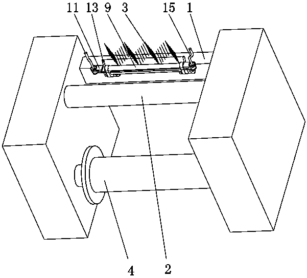
[0019] like Figures 1 to 3 As shown, it is used for the threading and splitting mechanism on the warping machine. The threading mechanism is fixedly arranged on the frame 1 of the warping machine, and is located between the guide roller 2 and the telescopic reed structure 3 of the warping machine. The threading mechanism includes a fixed The supports 6 arranged at the left and right ends of the frame 1 are horizontally rotated and provided with pulleys 7 of the same height, and a closed traction wire ring 8 is sleeved on the pulleys 7 at the left and right ends, and the traction wire ring 8 can be a steel wire Or a thin wire rope, which is specifically set as a thin wire rope here, and its two ends go around the outer end faces of the two pulleys 7 respectively, and the part of the traction wire ring 8 that is located in the middle of the two pulleys 7 is a two-section straight line section, and the two-section pulley The straight section is horizontal and at the same height....

Embodiment 2

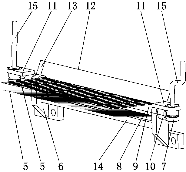
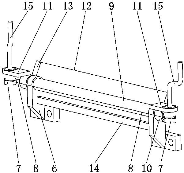
[0024] like figure 2 and 3 As shown, on the basis of Embodiment 1, it also includes warp yarn limit iron wire 12, and the two ends of warp yarn limit iron wire 12 are fixedly connected with two supports 6 respectively, specifically, the two ends of warp yarn limit iron wire 12 pass through respectively The fixing nail 13 is fixedly connected with the collars 10 at both ends, and the warp yarn limiter wire 12 is lower than the apex of the telescopic reed structure 3, preventing the warp yarn 5 from accidentally jumping to other warp yarn 5 intervals of the telescopic reed structure 3, causing the warp yarn 5 to be entangled, and the warp yarn limit The end of the position iron wire 12 is fixedly connected with the support 6 through a tension spring (not shown in the figure), so that when the warp yarn 5 is in contact with the warp yarn limit iron wire 12, the warp yarn limit iron wire 12 has a certain elastic buffer to prevent the warp yarn 5 from breaking .


PUM


Abstract

The invention relates to the field of warping operation assisting equipment and discloses a lease thread threading mechanism for a warping machine. The threading mechanism is fixedly arranged on a warping machine frame and positioned between a yarn guide roller and an adjustable reed structure of the warping machine and comprises supporting seats on left and right ends of the frame, pulleys identical in height are horizontally and rotationally arranged on the supporting seats, a closed pull thread loop sleeves the pulleys at the left and right ends, two ends of the closed pull thread loop bypass outer end faces of the two pulleys respectively, and portions, between the two pulleys, of the pull thread loop are two linear sections in horizontal arrangement at the same height. When one of thepulley rotates, the linear sections of the pull thread loop are driven to move linearly while the other pulley is driven to rotate through the pull thread loop, the pull thread loop penetrates warpsof the warping machine, each warp bypasses the upper end or the lower end of the pull thread loop, and adjacent warps are positioned at different ends of the pull thread loop. The threading mechanismis structurally simple and practical and quick and convenient to thread, labor intensity is reduced, and operating efficiency is improved.

Description

technical field [0001] The invention relates to the field of warping operation auxiliary equipment, in particular to a threading, splitting and stranding mechanism used on a warping machine. Background technique [0002] The purpose of warping is to wind a certain number of cheeses in parallel on the warp beam with appropriate and uniform tension according to the length and width required by the process design, so as to prepare for warp yarn sizing and weaving beams; in order to facilitate It is easy to separate the beams and sizing on the sizing machine to avoid yarn twisting when the yarn is sizing. It is necessary to add a split line to each warp beam during warping so that the warp yarns on the warp beam are divided into upper and lower parts. The sub-strands are axial lines. At present, there is no convenient device for the warping machine to thread the sub-strands. When threading the sub-strands, manual threading operation is required. Generally, there are many warp ya...

Claims


Application Information

Patent Timeline
IPC IPC(8): D02H9/00
Inventor 熊世清熊明清毛东军杨远明勾永安李秀芳陈果陈望
Owner SICHUAN YUYANG TEXTILE
Why Eureka
Try Eureka