
Centrifugal fan

A centrifugal fan and casing technology, which is applied in the direction of mechanical equipment, machine/engine, liquid fuel engine, etc., can solve problems that affect user experience, have no dust removal effect, and affect health, so as to improve user experience and ensure health. Healthy and convenience-enhancing effects

Active Publication Date: 2019-06-04
上海应达风机股份有限公司
View PDF8 Cites 0 Cited by
  • Summary
  • Abstract
  • Description
  • Claims
  • Application Information

AI Technical Summary

Problems solved by technology

The centrifugal fan has the following defects: 1. It has no dust removal effect. For the environment with serious dust, the airflow discharged by it will be accompanied by a large amount of dust, which will easily cause environmental pollution and affect people's health; 2. The centrifugal fan The airflow discharged by the centrifugal fan is fast and not uniform enough, which will cause obvious gas flow in the environment and affect the user experience

Method used


Image

  • Centrifugal fan
  • Centrifugal fan
  • Centrifugal fan

Examples


Embodiment Construction

[0034] The present invention will be described in detail below in conjunction with the accompanying drawings and embodiments.

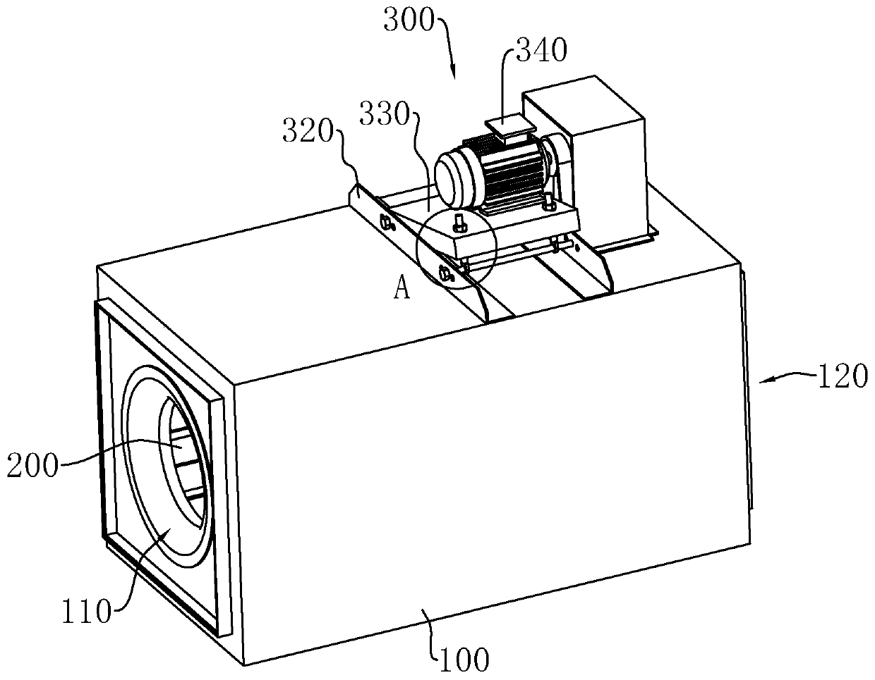
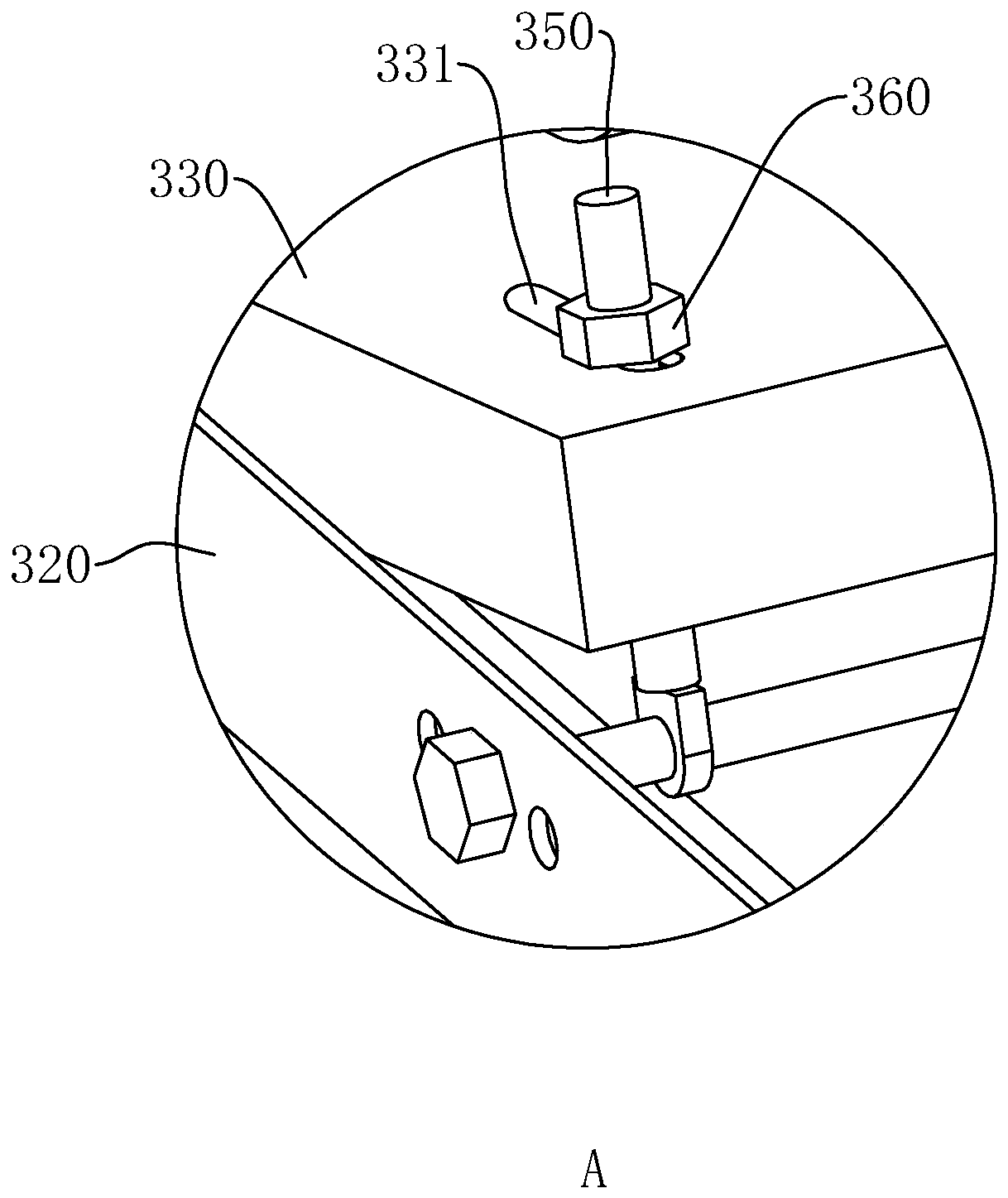
[0035] See attached figure 1 , a centrifugal fan, including a casing 100, the casing 100 has a cuboid or cube cavity structure, and the opposite sides of the casing 100 are respectively provided with an air inlet 110 and an air outlet 120; in this embodiment, the machine can be The sides where the air inlet 110 and the air outlet 120 are located on the casing 100 are respectively defined as the front side and the rear side of the casing 100 . The casing 100 is provided with a rotating impeller 200 , and the casing 100 is also provided with a driving assembly 300 for driving the impeller 200 to rotate. Wherein, the air inlet side of the impeller 200 is facing the air inlet 110, and the airflow will enter the impeller 200 immediately after entering the casing 100; as the impeller 200 continues to rotate, the airflow will be discharged from the peripher...


PUM


Abstract

The invention discloses a centrifugal fan, and relates to the technical field of fans. The centrifugal fan comprises a fan shell and an impeller, wherein the fan shell is correspondingly provided withan air inlet and an air outlet, an air flow guide cover is fixed to the inner wall of the fan shell, and the air out side of the impeller is surrounded by the air flow guide cover in a circumferential mode. An air flow guide opening is formed in the side, away from the air inlet, of the air flow guide cover, and an air flow guide surface for guiding air flow to move towards the air flow guide opening is formed on the inner wall of the air flow guide cover. The air flow guide cover is connected with an air filtering duct through the air flow guide opening, a plurality of air filtering holes are uniformly formed in the inner wall of the air filtering duct, and the air outlet communicates with the external space of the air filtering duct. The centrifugal fan is stable in operation, uniform in gas discharge and convenient to maintain, discharged gas can be purified, environmental pollution can be avoided, it is ensured that users are in good health, and user experience is high.

Description

technical field [0001] The invention relates to the technical field of fans, in particular to a centrifugal fan. Background technique [0002] The centrifugal fan is a machine that relies on the input mechanical energy to increase the gas pressure and distribute the gas. It is a driven fluid machine. Centrifugal fans are widely used for ventilation, dust removal and cooling in factories, mines, tunnels, cooling towers, vehicles, ships and buildings. [0003] The existing invention patent application with publication number CN104454585A discloses a stand-alone centrifugal fan with blade guide groove noise reduction, including a volute, a motor and an impeller. The volute is provided with an air inlet and an air outlet. In the middle part, the motor is fixed to the middle part of the volute through a support rod and coaxially connected with the impeller. [0004] With the above technical solution, the motor can drive the impeller to rotate, and the air enters the volute from...

Claims


Application Information

Patent Timeline
IPC IPC(8): F04D17/16F04D29/44F04D29/66F04D29/70
Inventor 应德池彭新华
Owner 上海应达风机股份有限公司
Learn More