Oil tank liquid level control exhaust valve with low dynamic leakage amount

A technology of liquid level control and leakage, which is applied in the direction of valves, valve details, valve devices, etc. for ventilation, which can solve the problems of large dynamic leakage, complex anti-leakage structure, low dynamic leakage, etc., and reduce the vacuum degree , solve the dynamic fuel leakage, reduce the effect of pressure drop

Inactive Publication Date: 2019-06-04
WUHU TYCO AUTOMOTIVE TECH CO LTD
View PDF0 Cites 0 Cited by
  • Summary
  • Abstract
  • Description
  • Claims
  • Application Information

AI Technical Summary

Problems solved by technology

[0007] The purpose of the present invention is to overcome the deficiencies in the prior art such as the large dynamic leakage of the fuel tank liquid level control exhaust valve and the complicated leakage prevention structure, and provide a fuel tank liquid level control exhaust valve with low dynamic leakage. This technical scheme can not only effectively reduce the dynamic leakage of the valve, but also the anti-leakage structure is simple and easy to manufacture

Method used


Image

  • Oil tank liquid level control exhaust valve with low dynamic leakage amount
  • Oil tank liquid level control exhaust valve with low dynamic leakage amount
  • Oil tank liquid level control exhaust valve with low dynamic leakage amount

Examples


Embodiment 1

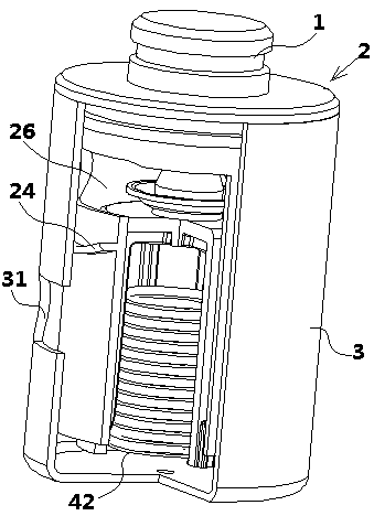
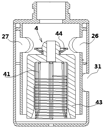
[0035] Such as figure 1 , figure 2 , image 3 with Figure 4As shown, a fuel tank liquid level control exhaust valve with low dynamic leakage in this embodiment includes a valve body 2, a housing 3 sleeved on the outside of the valve body 2 and a float located in the inner cavity of the valve body 2 Assembly 4, wherein, the float assembly 4 of the present embodiment includes a spring support 41, a spring 42, a float 43 and a sealing plate 44, the spring support 41 includes a plurality of supports, and the plurality of supports surround a cylindrical support, and the cylindrical support A spring 42 is set on the outside of the bracket, and a float 43 is set on the outside of the spring 42. The lower end of the float 43 is a trumpet-shaped opening, and a sealing sheet 44 is provided on its upper end. The inside surface of the inner surface is provided with a clamping bar engaged with the above-mentioned clamping groove, and the matching setting of the clamping groove and the...

Embodiment 2

[0039] A fuel tank liquid level control exhaust valve with low dynamic leakage in this embodiment has the same basic structure as that in Embodiment 1, except that the exhaust port I26 in this embodiment is located on the front of the valve body 2, and the valve The back of the body 2 is also provided with an exhaust port II 27. In this embodiment, the exhaust port II 27 is provided on the back of the valve body 2, so that the oil and gas in the fuel tank can be discharged through more gas channels, such as Figure 5 As shown, the oil and gas can be discharged through the air inlet 31, the exhaust port I26 and then through the air outlet on the valve body 2 (that is, the A gas channel), or the oil and gas can be discharged through the air inlet 31, the exhaust port II27 and then through the valve body 2 It should be emphasized that this implementation effectively reduces the vacuum degree near the sealing sheet 44 by reasonably setting the positional relationship between the A ...

Embodiment 3

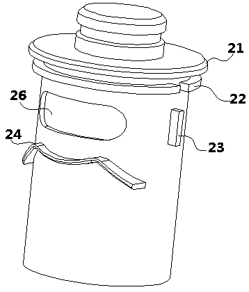
[0041] A fuel tank liquid level control exhaust valve with low dynamic leakage in this embodiment has the same basic structure as that in Embodiment 2, the difference is that in this embodiment, it is below the exhaust port II 27 and on the side of the valve body 2 The limit block II25 is arranged on the top, and the limit block II25 is arranged along the circumferential direction of the side of the valve body 2. The limit block I23 is arranged on the side of the valve body 2 between the exhaust port I26 and the exhaust port II27, and the limit block I23 is arranged along the valve body. The axial arrangement of the body 2, in this embodiment, by setting the limit block I23 and the limit block II25 on the side of the valve body 2, the position eccentricity of the valve body 2 and the shell 3 during assembly or welding is effectively avoided, ensuring that the valve The coaxiality of body 2 and shell 3.


PUM


Abstract

The invention discloses an oil tank liquid level control exhaust valve with low dynamic leakage amount, and belongs to the field of exhaust valves. The oil tank liquid level control exhaust valve comprises a valve body, a shell arranged on the outer side the valve body in a sleeving mode and a float assembly located in an inner cavity of the valve body. A gas inlet is formed in the side surface ofthe shell, an exhaust port I is formed in the side surface of the valve body, an oil baffle plate is arranged above the gas inlet, and the oil baffle plate is disposed between the side surface of theshell and the side surface of the valve body; and the two side surfaces of the oil baffle plate are separately attached to the side surface of the valve body and the side surface of the shell, the two ends of the oil baffle plate separately extend in the circumferential direction of the valve body, the length of the oil baffle plate is greater than the length of the exhaust port I in the circumference direction of the valve body, and the exhaust port I is located above the oil baffle plate. According to the technical scheme, the dynamic leakage amount of the valve can be effectively reduced,the anti-leakage structure is simple, and manufacturing is simple.

Description

technical field [0001] The invention relates to the technical field of exhaust valves, in particular to an oil tank liquid level control exhaust valve with low dynamic leakage. Background technique [0002] At present, GB18352-2016 "Limits and Measurement Methods of Pollutant Emissions from Light-duty Vehicles" raises the implementation of pollutant emissions from light-duty vehicles from the fifth stage to the sixth stage and will be implemented in 2020, which poses new challenges to the fuel system. The new challenge is mainly that the evaporative emission of hydrocarbons from the whole vehicle increased from 2 grams / test to 0.7 grams / test. At the same time, the requirement for online refueling vapor recovery was put forward, which also determined the vapor management on the fuel tank. Valves in these areas are more specific and demanding in order to achieve this goal. [0003] For the valve of the automobile fuel tank, there is a main valve body called the liquid level c...

Claims


Application Information

Patent Timeline
Patent Type & Authority Applications(China)
IPC IPC(8): F16K24/04F16K31/22F16K27/02B60K15/03
Inventor 杨结海
Owner WUHU TYCO AUTOMOTIVE TECH CO LTD
Why Eureka
Try Eureka