
A precise positioning method for a target reporting system and a target reporting system

A technology for precise positioning and target reporting, which is applied in the field of target systems, can solve the problems of image recognition system with high hardware computing power requirements, slight overlap of bullet holes, and error in target reporting accuracy, etc. Replacement, high precision effect

Active Publication Date: 2021-12-07
南京强钧防务科技研究院有限公司
View PDF4 Cites 0 Cited by
  • Summary
  • Abstract
  • Description
  • Claims
  • Application Information

AI Technical Summary

Problems solved by technology

The defects of the system using a single ultrasonic technology are: 1. Since the transmission speed of the ultrasonic wave is affected by various external factors such as air temperature and air pressure, the accuracy error of the target reporting cannot be controlled below 5mm; 2. When changing the target paper, the target paper is required. The position is accurately attached to the fixed position of the target paper, or additional correction methods are required, otherwise target reporting errors will occur
The target reporting system using a single image recognition technology has a high target reporting accuracy, but the disadvantages are: 1. It is difficult to distinguish the "bullet holes" produced by non-bullets or ricochets from the bullet holes formed by real bullets, so it is easy to produce False alarms; 2. In live ammunition shooting, there will often be slight overlap or even complete overlap of bullet holes. A single image recognition system cannot detect this difference, and it is prone to false alarms; 3. If the image recognition target reporting system needs to To achieve real-time target reporting, the algorithm needs to monitor the image changes in the entire target range in real time throughout the whole process, which requires high computing power for the image recognition system hardware

Method used


Image

  • A precise positioning method for a target reporting system and a target reporting system
  • A precise positioning method for a target reporting system and a target reporting system
  • A precise positioning method for a target reporting system and a target reporting system

Examples


Embodiment Construction

[0030] The present invention will be further described below in conjunction with the accompanying drawings and embodiments.

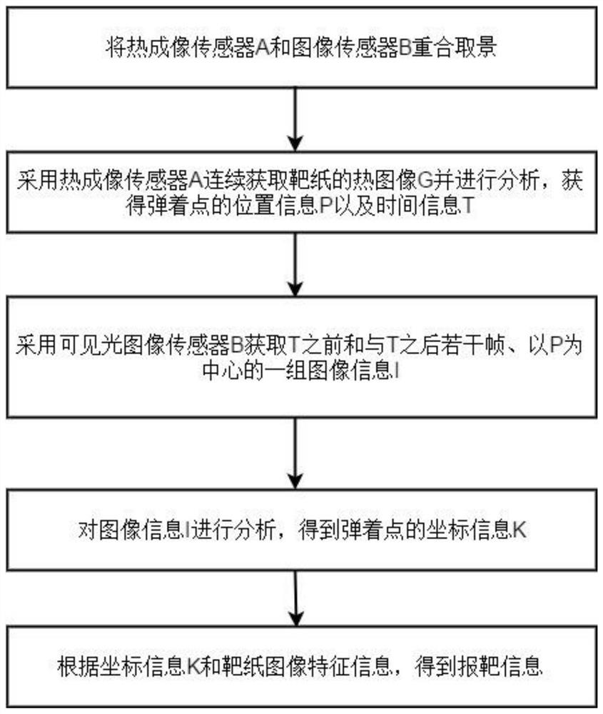
[0031] Such as figure 1 As shown, embodiment 1 provides a kind of accurate positioning method of target reporting system, mainly comprises:

[0032] Overlap the thermal imaging sensor A and the visible light image sensor B;

[0033] Using the thermal imaging sensor A to continuously acquire and analyze the thermal image G of the target paper, and obtain the initial spatial coordinate information P and time information T of the bullet penetrating the target paper (point of impact);

[0034] Visible light image sensor B is used to acquire a set of image information I centered on P in several frames before T and after T;

[0035]Analyze the local target paper image I to obtain the precise coordinate information K of the impact point;

[0036] According to the precise coordinate information K and the characteristic information of the target paper image, ...


PUM


Abstract

The invention discloses a precise positioning method for a target reporting system, which comprises: overlapping a thermal imaging sensor and an image sensor for framing; using the thermal imaging sensor to continuously acquire thermal images of target paper, and analyzing the thermal images to obtain initial coordinate information P of the impact point and time information T; use a visible light image sensor to continuously acquire image H, select several frames before T and after T in image H, a group of image information I centered on P; analyze I to obtain precise coordinate information K of the impact point; Extract the target paper image feature information in the image H; obtain the target report information according to the precise coordinate information K and the target paper image feature information. Further, a target reporting system is also disclosed. The invention can effectively eliminate false alarms generated when other non-bullets penetrate the target paper, and the analysis difficulty and required time are greatly reduced, the implementation is simpler, the use is more convenient, and the acquisition of target information is more accurate and reliable.

Description

technical field [0001] The invention belongs to the technical field of target systems, and relates to a precise positioning method for a target reporting system and the target reporting system. Background technique [0002] At present, in the automatic target reporting system for live ammunition shooting with light weapons, the core method for detecting the position of the impact point is mainly based on ultrasonic technology or image recognition technology. The defects of the system using a single ultrasonic technology are: 1. Since the transmission speed of ultrasonic waves is affected by various external factors such as air temperature and air pressure, the accuracy error of the target reporting cannot be controlled below 5mm; 2. When changing the target paper, the target paper is required. The position is accurately attached to the fixed position of the target paper, or additional correction methods are required, otherwise target reporting errors will occur. The target ...

Claims


Application Information

Patent Timeline
Patent Type & Authority Patents(China)
IPC IPC(8): F41J5/02
Inventor 赵文龙戚海峰
Owner 南京强钧防务科技研究院有限公司
Learn More