
Waveguide display device

A display device and waveguide technology, applied in the optical field, can solve the problems of low luminous flux conversion efficiency, low contrast, large heat generation, etc., and achieve the effects of low power consumption, high luminous flux conversion efficiency, and low heat generation

Inactive Publication Date: 2019-06-04
JOURNEY TECH LTD
View PDF2 Cites 11 Cited by
  • Summary
  • Abstract
  • Description
  • Claims
  • Application Information

AI Technical Summary

Problems solved by technology

It aims to solve the problems of high power consumption, high heat generation, low luminous flux conversion efficiency, low color gamut, and low contrast in augmented reality display devices

Method used


Image

  • Waveguide display device
  • Waveguide display device
  • Waveguide display device

Examples


Embodiment Construction

[0026] The following description and drawings illustrate specific embodiments of the invention sufficiently to enable those skilled in the art to practice them. The examples merely represent possible variations. Individual components and functions are optional unless explicitly required, and the order of operations may vary. Portions and features of some embodiments may be included in or substituted for those of other embodiments. The scope of embodiments of the present invention includes the full scope of the claims, and all available equivalents of the claims. Herein, various embodiments may be referred to individually or collectively by the term "invention", which is for convenience only and is not intended to automatically limit the scope of this application if in fact more than one invention is disclosed. A single invention or inventive concept. Herein, relational terms such as first and second etc. are used only to distinguish one entity or operation from another with...


PUM


Abstract

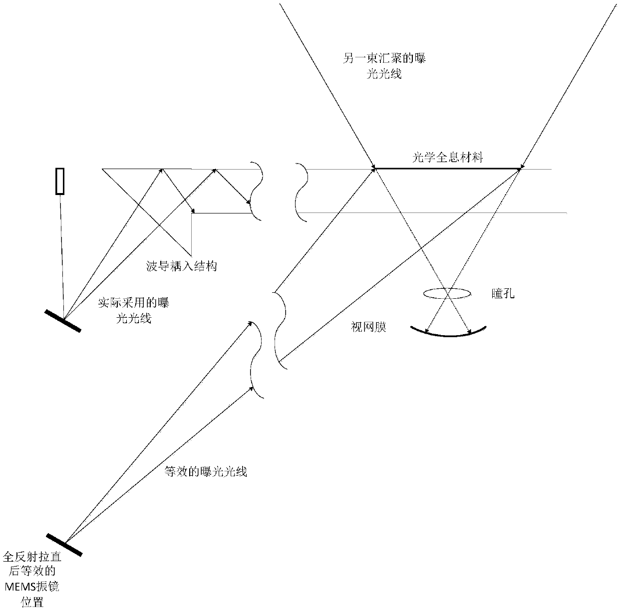
The invention discloses a waveguide display device, which relates to the technical field of optics. The waveguide display device comprises a laser light source, a micro electro mechanical system MEMSgalvanometer, a waveguide coupling-in structure, an optical diffraction structure and a waveguide, wherein the laser light source is used for generating a laser beam; the MEMS galvanometer is used forcontrolling the laser beam generated by the laser light source to emit to the waveguide coupling-in structure; the waveguide coupling-in structure is used for coupling the laser beam into the waveguide; and the optical diffraction structure is used for coupling out the laser beam propagated in the waveguide in a designed direction. The waveguide display device disclosed by the invention has the advantages of low power consumption, low heat productivity, high luminous flux conversion efficiency, wide color gamut and high contrast ratio.

Description

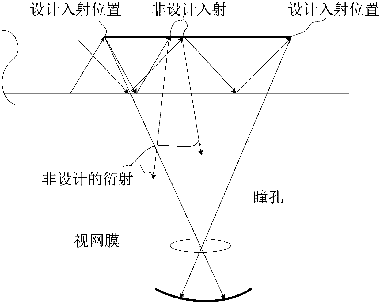
technical field [0001] The invention relates to the field of optical technology, in particular to a waveguide display device. Background technique [0002] Near-eye display technology is more and more widely used in virtual reality and augmented reality display devices. In the prior art, the optical outcoupling structures adopted by near-eye display devices mainly include reflective arrays, holographic gratings, and embossed gratings. The common point is that parallel light in different directions is coupled into the optical waveguide. The range of this direction is the angle of view. , the parallel light at each viewing angle has a certain width, and the width of the beam is expanded through the exit pupil expansion, which has problems such as low brightness. In order to solve this problem, LED or UHP light bulbs are often used as light sources in the prior art, but at the same time, these light sources also have problems such as high power consumption, high heat generatio...

Claims


Application Information

Patent Timeline
IPC IPC(8): G02B27/01G02B27/10
Inventor 闫冠屹郑昱
Owner JOURNEY TECH LTD
Features
  • Generate Ideas
  • Intellectual Property
  • Life Sciences
  • Materials
  • Tech Scout
  • Unparalleled Data Quality
  • Higher Quality Content
  • 60% Fewer Hallucinations
Learn More