Photonic crystal super-resolution imaging device with variable period grating

A super-resolution imaging and photonic crystal technology, applied in optical components, instruments, optics, etc., can solve the problems of photonic crystals, such as the absence of simultaneously negative permittivity and permeability, and the controversy over the super-resolution imaging mechanism. The effect of breaking through the diffraction limit and improving imaging resolution

Inactive Publication Date: 2021-04-20
UNIV OF SHANGHAI FOR SCI & TECH
View PDF8 Cites 0 Cited by
  • Summary
  • Abstract
  • Description
  • Claims
  • Application Information

AI Technical Summary

Problems solved by technology

[0003] However, because photonic crystals do not have both negative permittivity and magnetic permeability, the mechanism of super-resolution imaging is still controversial.
In addition, the resolution of photonic crystal imaging is only slightly smaller than the diffraction limit, and further work is still needed to continue to improve the imaging resolution of photonic crystals

Method used


Image

  • Photonic crystal super-resolution imaging device with variable period grating
  • Photonic crystal super-resolution imaging device with variable period grating
  • Photonic crystal super-resolution imaging device with variable period grating

Examples


Embodiment Construction

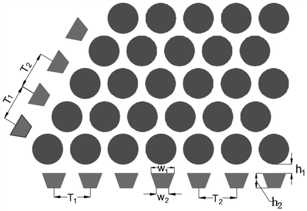
[0017] First, the parameters of the photonic crystal are designed so that the equivalent refractive index is -1. The background material is a silicon medium with a refractive index of n=3.45, and air columns are arranged periodically in the silicon medium in a hexagonal lattice. Air column radius r = 193.5nm, lattice constant a = 482nm.

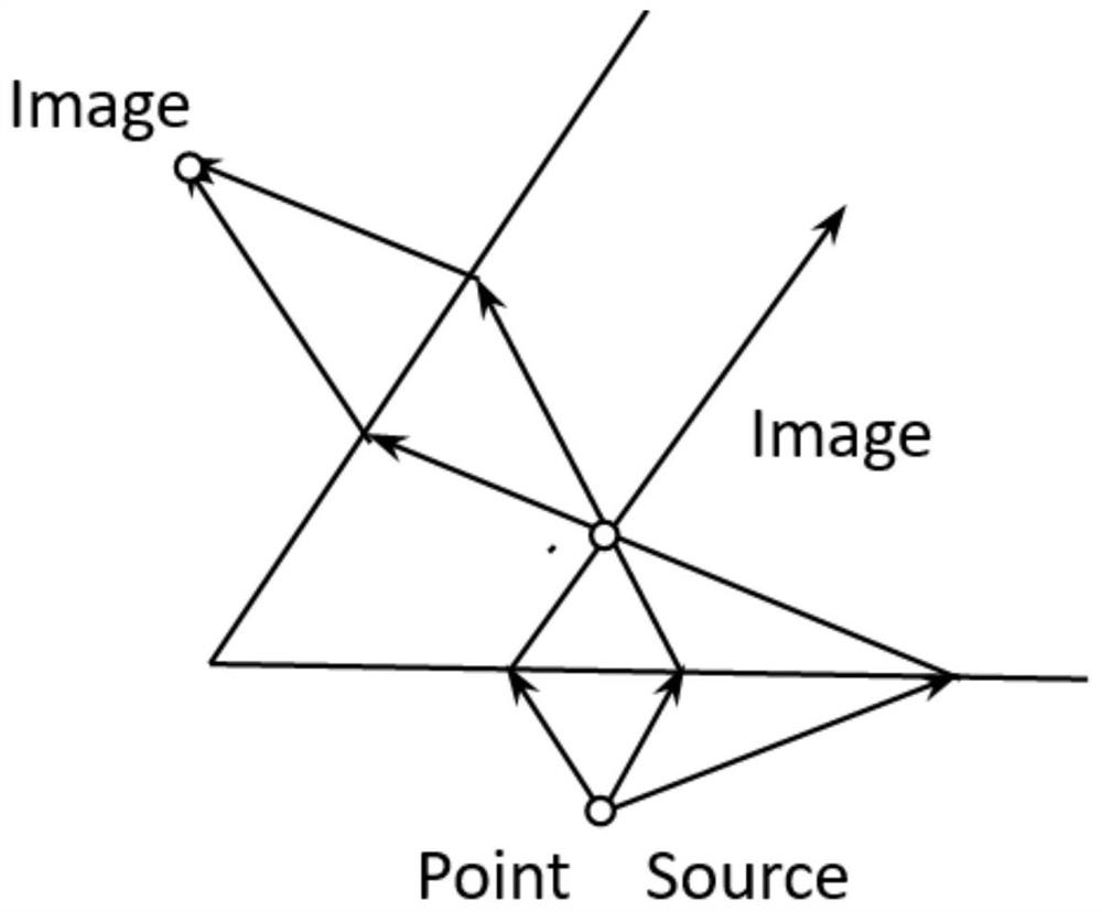
[0018] like figure 1 The schematic diagram of the photonic crystal imaging process is shown. The point source (Point Source) is placed in the near-field range below the photonic crystal. After negative refraction, a virtual image point (Image) is formed inside the photonic crystal, and the internal image point is negatively refracted. It acts on the external image space of the photonic crystal for imaging. Because the photonic crystal has an equivalent refractive index of -1, it can amplify the evanescent wave of the light source and achieve imaging that breaks through the diffraction limit. However, the surface structure of the photonic c...


PUM


Abstract

The invention relates to a variable-period grating photonic crystal super-resolution imager. There is a gap of the same width between the incident surface of the crystal and the exit surface of the photonic crystal. The equivalent refractive index of the photonic crystal is -1. The number of columns, the point light source enters the photonic crystal after passing through the sub-wavelength grating, and realizes super-resolution imaging that breaks through the diffraction limit. By adding a sub-wavelength grating on the surface of the photonic crystal, the coupling effect of the light field is enhanced, the half-width of the image point is compressed, the imaging resolution is improved and the diffraction limit is broken.

Description

technical field [0001] The invention relates to an imaging technology, in particular to a variable-period grating photonic crystal super-resolution imager. Background technique [0002] The former Soviet scientist Veselego first proposed the concept of "negative refraction" in 1968, and theoretically predicted that in this negative refraction material, the electric field, magnetic field, and wave vector direction no longer conform to the right-hand rule of traditional materials, but obey the left-hand rule, so This material is also called "left-handed material". It is also predicted that in materials with negative permittivity ε and magnetic permeability μ at the same time, negative refraction will occur, that is, the incident wave and outgoing wave are located on the same side of the normal. However, it was not until the beginning of this century that D.R.Smith and others experimentally prepared artificial materials capable of negative refraction. This material is composed...

Claims


Application Information

Patent Timeline
Patent Type & Authority Patents(China)
IPC IPC(8): G02B27/58
Inventor 王国旭梁斌明
Owner UNIV OF SHANGHAI FOR SCI & TECH
Why Eureka
Try Eureka