Solenoid valve for controlling the braking pressure of a wheel brake and tool for producing its valve element

A wheel brake and brake pressure technology, applied in the direction of brakes, engine components, electromagnets with armatures, etc., can solve the problems of different magnetic forces, fluctuations, etc., and achieve the effect of improving accuracy and reducing armature tilt

Active Publication Date: 2019-06-04
ROBERT BOSCH GMBH
View PDF7 Cites 0 Cited by
  • Summary
  • Abstract
  • Description
  • Claims
  • Application Information

AI Technical Summary

Problems solved by technology

In addition, different component orientations between armature and tappet can lead to fluctuations during pressure adjustment (e.g. in figure 2 as shown in ), because a large number of different situations and thus different magnetic forces can occur between the armature and the tappet

Method used


Image

  • Solenoid valve for controlling the braking pressure of a wheel brake and tool for producing its valve element
  • Solenoid valve for controlling the braking pressure of a wheel brake and tool for producing its valve element
  • Solenoid valve for controlling the braking pressure of a wheel brake and tool for producing its valve element

Examples


Embodiment Construction

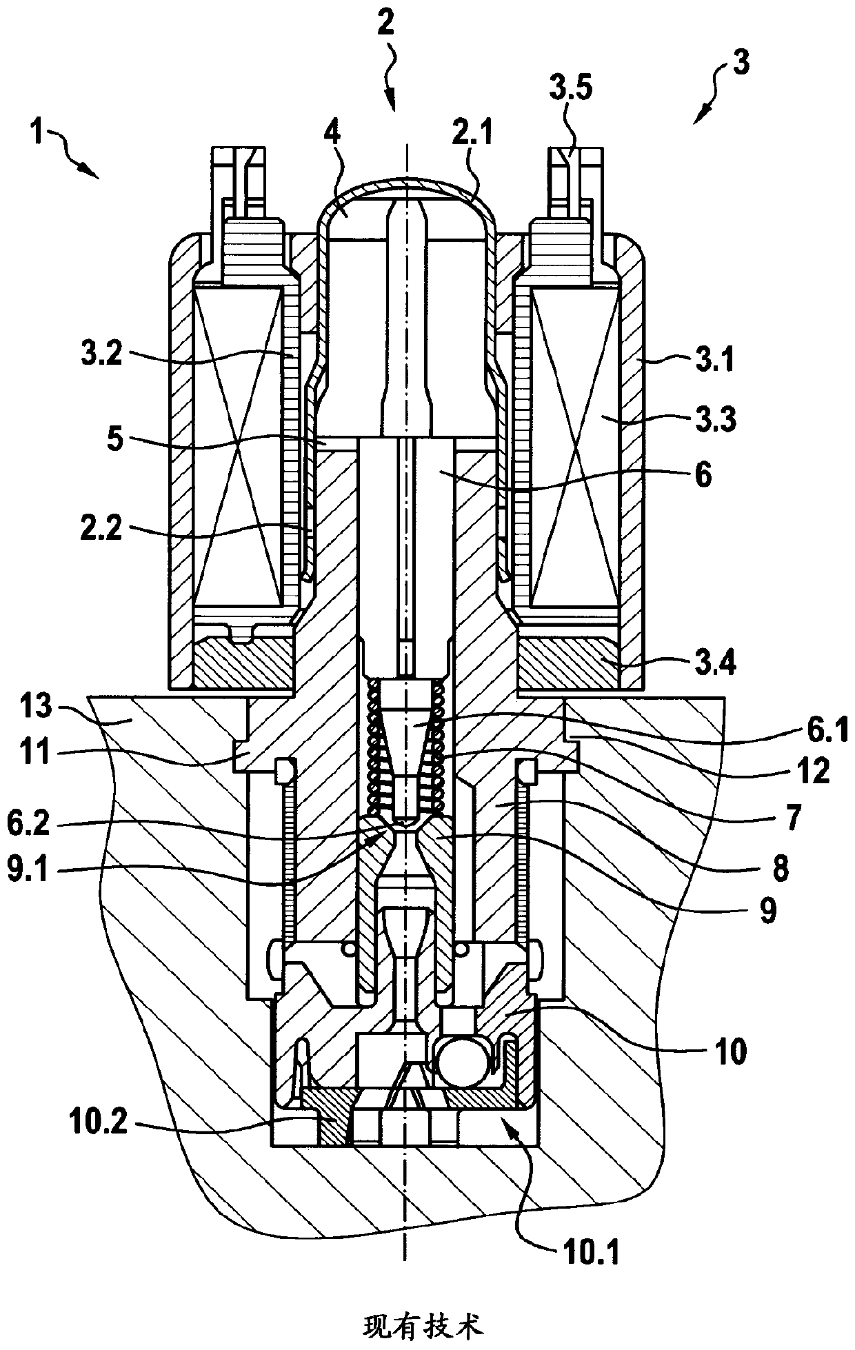
[0044] exist figure 1 A schematic cross-sectional view of a conventional solenoid valve is shown in . Such solenoid valves have already been described as prior art.

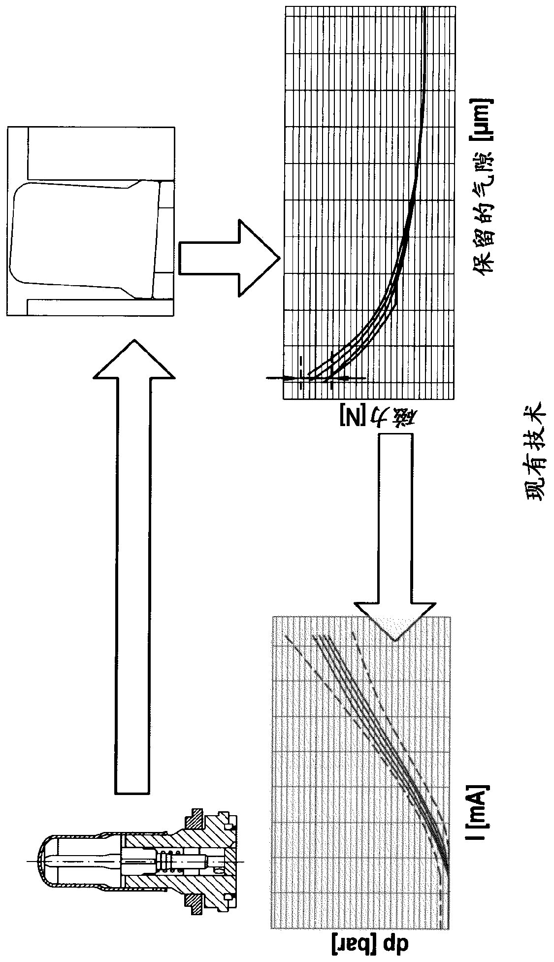
[0045] also, figure 2 The causal chain is shown schematically. In this case, possible tolerances in the individual components are shown in the illustration in the upper left corner. Such deviations can lead to tilting or to a tilted position of the armature, for example with respect to the valve seat. This is shown in the upper right corner of the illustration. During use of the valve, rotation of the armature and / or the valve element may also occur. The rotation results in an oblique position of the armature, for example with respect to the valve seat. However, a varying tilted position of the armature results in a varying magnetic force acting on the armature. This is shown in the lower right corner of the illustration. The varying magnetic force acting on the armature in turn leads to different curren...


PUM


Abstract

The present invention relates to a solenoid valve (1) for controlling the braking pressure of a wheel brake of a slip-controllable hydraulic brake system of a motor vehicle, having a valve element (6)arranged at least partially in a valve insert (8) in a longitudinally displaceable manner and acting together with a valve seat (9.1), to which valve element, in the installed position, a force component acting in the direction of opening with respect to the valve seat (9.1) is applied by a spring device (7), wherein: the valve element can be actuated by means of an electromagnetic actuator (3) in the closing direction with respect to the valve seat (9.1); the valve element (6) is arranged between an anchor (4) and the valve seat (9.1) and is operatively connected to the anchor (4); the solenoid valve (1) is characterised in that a front face (6.4) of the valve element (6) facing the anchor (4) has at least one projection (6.3); and the projection (6.3) defines a point of contact with theanchor (4). The present invention further relates to a tool for producing the valve element (6).

Description

technical field [0001] The invention relates to a solenoid valve for controlling the brake pressure of the wheel brakes of a slip-adjustable hydraulic brake system of a motor vehicle, the solenoid valve having a valve at least partially arranged in a longitudinally movable manner A valve element in the seat and cooperating with the valve seat, which is loaded by a spring device in the installed position with a force component acting in the opening direction with respect to the valve seat and which can be controlled by means of an electromagnetic actuator The valve seat is actuated in the closing direction, wherein the valve element is arranged between an armature and the valve seat and is in operative connection with the armature, wherein the solenoid valve is characterized in that the valve element The end face facing the armature has at least one projection, wherein the projection defines a contact point with the armature. Background technique [0002] Patent application ...

Claims


Application Information

Patent Timeline
Patent Type & Authority Applications(China)
IPC IPC(8): B60T8/36F16K31/06
CPCB60T8/363F16K31/0665B60T8/36B60T13/686F16K27/00F16K31/0675H01F7/16B60Y2400/81
Inventor M·埃特勒K·兰德斯费德J·诺伯格S·斯泰加斯T·魏茨C·博德曼E·斯泰布
Owner ROBERT BOSCH GMBH
Why Eureka
Try Eureka