Eureka AIR delivers breakthrough ideas for toughest innovation challenges, trusted by R&D personnel around the world.

Dual-riser petroleum hydrocarbon feed stock catalytic conversion method and device

A catalytic conversion method and double riser technology are applied in the field of double riser catalytic conversion of petroleum hydrocarbon raw materials, which can solve problems such as increasing the feasibility of engineering implementation, reduce thermal cracking reaction, improve catalytic conversion reaction, and improve oil-agent contact. the effect of the situation

Inactive Publication Date: 2014-07-16
QINGDAO JINGRUN PETROCHEM DESIGN INST CO LTD
View PDF5 Cites 2 Cited by
  • Summary
  • Abstract
  • Description
  • Claims
  • Application Information

AI Technical Summary

Problems solved by technology

In order to improve the reaction efficiency of heavy feedstock oil in the riser reactor, there have been many inventions to improve the activity of the catalyst in the second half of the reactor. CN1302843A proposed a catalyst relay scheme, that is, the catalyst is replaced in the middle of the riser, and the reaction The exhausted catalysts are all separated and replaced with high-activity, low-temperature regenerated catalysts after cooling treatment, so that the efficiency of the second half of the riser can be completely restored to the efficiency of the first half. Although this solves the previous problem, it increases the feasibility of project implementation. sex

Method used

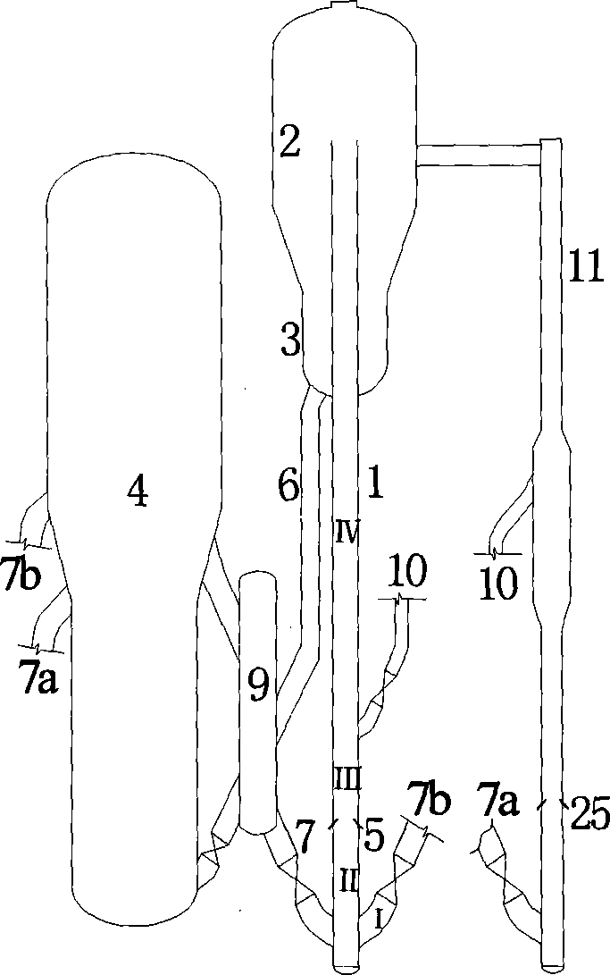
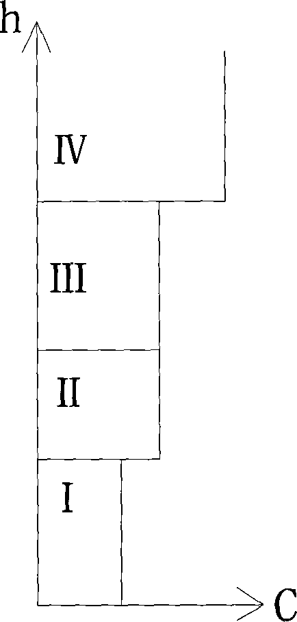

Image

  • Dual-riser petroleum hydrocarbon feed stock catalytic conversion method and device
  • Dual-riser petroleum hydrocarbon feed stock catalytic conversion method and device
  • Dual-riser petroleum hydrocarbon feed stock catalytic conversion method and device

Examples


Embodiment 1

[0036] Example 1: see figure 1 . The temperature-reduced regenerated catalyst that enters from the regeneration riser 7 and is cooled by the catalyst cooler 9 is mixed with a part of the hot regenerated catalyst that enters from the regeneration riser 7b in the pre-lift section II at the bottom of the heavy raw material riser reactor 1. The atomized heavy raw material entering through the feed nozzle 5 is contacted to participate in the catalytic reaction, and the reaction mixture is upwardly contacted with the active relay catalyst from the light raw material riser reactor 11 through the catalyst relay pipe 10 and enters the reaction section IV to continue reaction to complete the catalytic conversion of heavy raw materials; a part of the hot regenerated catalyst enters the bottom of the light raw material riser reactor 11 from the regeneration standpipe 7a, and under the action of the lifting medium, it is upwardly connected with the atomized light raw material that enters t...

Embodiment 2

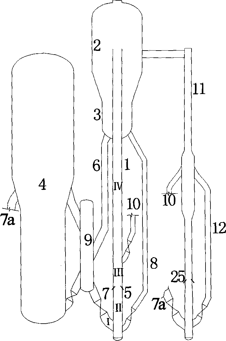
[0038] Example 2: see image 3 . After the self-reflux standby catalyst from the catalyst return pipe 8 is mixed with the cooled regenerated catalyst formed by the regeneration standpipe 7 and cooled by the catalyst cooler 9 in the pre-lift section II at the bottom of the heavy raw material riser reactor 1, Upward contact with the atomized heavy feedstock oil entering through the feed nozzle 5 to participate in the catalytic reaction; the reaction mixture upwardly contacts with the active relay catalyst from the light raw material riser reactor 11 introduced by the catalyst relay pipe 10 and reacts afterwards Section IV continues to react to complete the catalytic conversion of heavy raw materials; a part of the hot regenerated catalyst enters the bottom of the light raw material riser reactor 11 from the regeneration standpipe 7a, and under the action of the lifting medium, it is separated from the light raw material riser reactor 11. After being mixed with the self-refluxed...

Embodiment 3

[0039] Embodiment 3: see Figure 4 . The cooled regenerated catalyst that enters from the regeneration standpipe 7 and is cooled by the catalyst cooler 9 enters the pre-lift section II at the bottom of the heavy raw material riser reactor 1, and upwardly meets the atomized heavy raw material oil that enters through the feed nozzle 5. The contact participates in the catalytic reaction; the reaction mixture is upwardly contacted with the active relay catalyst from the light raw material riser reactor 11 through the catalyst relay pipe 10, and continues to react in the post-reaction section IV to complete the catalytic conversion of the heavy raw material; a part of the heat The regenerated catalyst enters the bottom of the light raw material riser reactor 11 from the regeneration standpipe 7a. Under the action of the lifting medium, it mixes with the self-reflux standby catalyst that is refluxed from the rear reaction section of the light raw material riser reactor 11. The atom...


PUM


Abstract

A catalytic conversion process of petroleum hydrocarbons in double reactor, and apparatus thereof are disclosed. The catalytic conversion process takes place in both the main reactor and the secondary reactor where reaction feedstock is lighter than the former. The first low temperature catalyst is introduced into the pre-lift section of the main reactor, and the said catalyst is conveyed to the oil / catalyst contact reaction section by the pre-lift gas and contacts with the feedstock from the feeding nozzle for the catalytic conversion reaction. The reaction mixture goes up and contacts with the second low temperature catalyst fed to the main reactor above the feeding nozzle, and the catalytic conversion reaction continues in the post-reaction section so as to complete the catalytic conversion reaction of the feedstock from the main reactor. Through flexible control over the reaction condition of the contact reaction section and post-reaction section of the reactor,thermal cracking reaction is effectively reduced, the reacting efficiency of the post-reaction section is improved. Accordingly, the reaction byproduct is effectively reduced and the product distribution is flexibly modified.

Description

technical field [0001] The invention relates to the field of petrochemical technology, in particular to a method and device for catalytic conversion of petroleum hydrocarbon raw materials with double risers. Background technique [0002] Catalytic conversion is an important secondary processing method for petroleum heavy fractions. Almost all existing petroleum hydrocarbon feedstock catalytic conversion devices use riser reactors, and the reaction raw materials are catalytically converted in the riser reactors to form gasoline, diesel, liquefied petroleum gas, etc. Reaction product. [0003] Conventional catalytic conversion methods and devices use riser reactors, and there are obvious deficiencies in the reaction process. First, the temperature of the regenerated catalyst is relatively high, which limits the ratio of reactants to oil and the preheating temperature of heavy oil. In the existing catalytic conversion reaction process, the reaction raw materials When the oil i...

Claims


Application Information

Patent Timeline
Patent Type & Authority Patents(China)
IPC IPC(8): C10G51/06
CPCC10G51/06B01J8/1809C10G51/026C10G11/187B01J8/26
Inventor 石宝珍
Owner QINGDAO JINGRUN PETROCHEM DESIGN INST CO LTD
Why Eureka
Eureka Blog
Learn More