Rotor cage bar and end ring welding bench and welding method

A rotor cage and processing table technology, which is applied in metal processing, welding equipment, auxiliary welding equipment, etc., can solve the problems of low welding efficiency, and achieve the effects of high welding efficiency, uniform tightening force, and reduction of uneven force.

Inactive Publication Date: 2019-06-07
西安阿尔斯通永济电气设备有限公司
View PDF10 Cites 0 Cited by
  • Summary
  • Abstract
  • Description
  • Claims
  • Application Information

AI Technical Summary

Problems solved by technology

[0005] Although this welding processing table can be used for welding the rotor cage bars and end rings, because it can only weld one group of rotor cage bars and end rings at a time, the welding efficiency is low

Method used


Image

  • Rotor cage bar and end ring welding bench and welding method
  • Rotor cage bar and end ring welding bench and welding method
  • Rotor cage bar and end ring welding bench and welding method

Examples


Embodiment 1

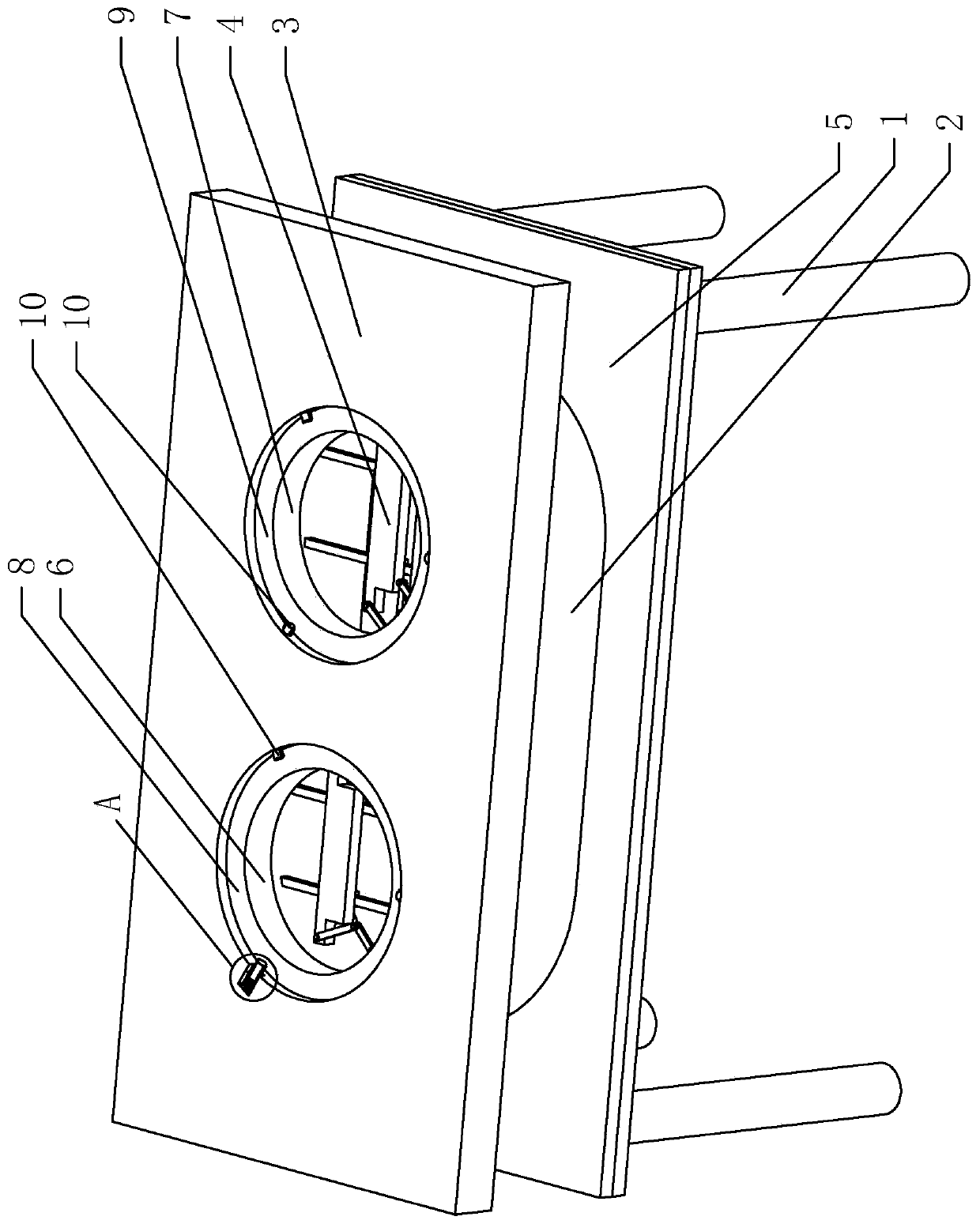
[0040] Embodiment 1: A rotor cage bar and end ring welding processing platform, such as figure 1 As shown, it includes a bracket 1 , a welding cylinder 2 , a workbench 3 and a clamping device 4 .

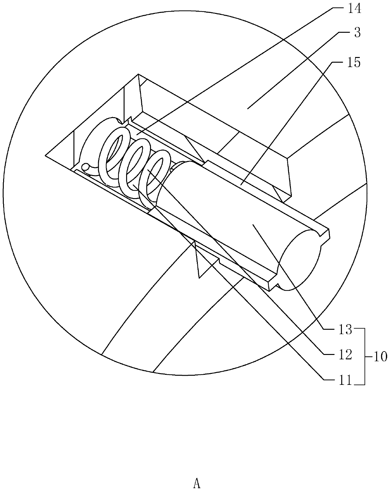
[0041] Such as figure 1 with figure 2 As shown, one end of the welding cylinder 2 is connected to the support 1, and the other end is connected to the worktable 3. The welding cylinder 2 is provided with a welding plate 5, which is welded with the support 1. The workbench 3 is provided with a first welding hole 6, a second Two welding holes 7, the first limiting groove 8 and the second limiting groove 9, the first welding hole 6 and the second welding hole 7 are all communicated with the welding cylinder 2, and the center line of the first limiting groove 8 is connected with the first limiting groove The centerlines of the positioning holes 11 are collinear, the centerlines of the second limiting groove 9 are collinear with the centerlines of the second limiting holes 11, the sid...

Embodiment 2

[0048] Embodiment 2: A method for welding rotor cage bars and end rings, which includes the following steps:

[0049] S1: brush flux, brush the flux on the surface of the rotor cage:

[0050] S2: Assemble, place the end ring in the first limit groove 8 and the second limit groove 9 of the workbench 3, and make the limit rod 13 touch the side wall of the end ring, and place the rotor cage on the workbench 3 , so that the end of the rotating cage is in the annular groove of the end ring;

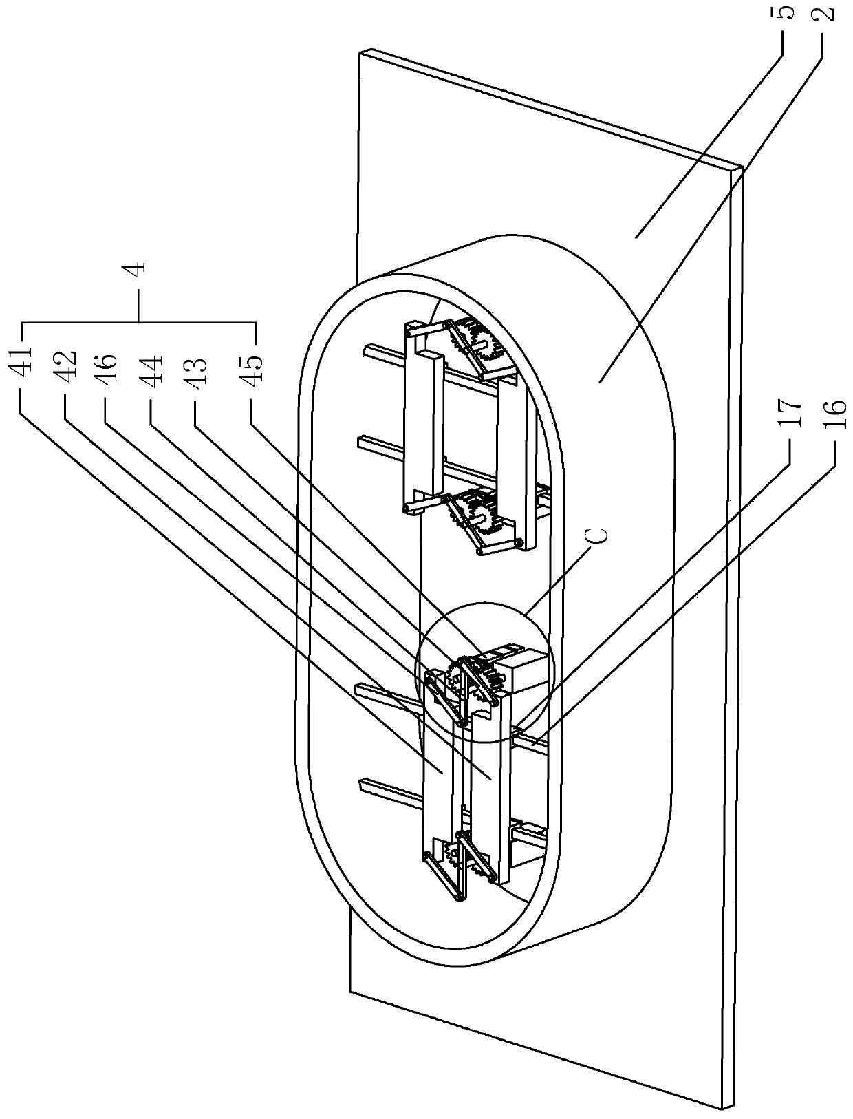
[0051] S3: Clamping, start the motor 451 to move the first clamping arm 41 and the second clamping arm 42 toward each other, the first clamping arm 41 and the second clamping arm 42 clamp the rotating shaft 22 of the motor 451, Fixed motor 451 rotating shaft 22;

[0052] S4: Welding, using a high-frequency induction welding machine to weld the rotor cage bar and the end ring together, the solder is silver-based brazing solder, and the flux is silver-based brazing flux.


PUM


Abstract

The invention relates to the technical field of motor welding, and aims to provide a rotor cage bar and end ring welding bench. According to the key points of the technical scheme, the rotor cage barand end ring welding bench comprises a support, a welding barrel and a workbench. A first welding hole, a second welding hole, a first limiting groove and a second limiting groove are formed in the workbench, and the first welding hole and the second welding hole communicate with the welding barrel. Limiting components are arranged on the side wall of the first limiting groove and the side wall ofthe second limiting groove, and each limiting component comprises a limiting hole, a spring and a limiting rod. The limiting holes are formed in the side wall of the first limiting groove and the side wall of the second limiting groove, one end of each spring is connected with the corresponding limiting hole, and the other of the spring is connected with the corresponding limiting rod. When the spring is under compression, the end, back from the spring, of the corresponding limiting rod is outside the corresponding limiting hole. The rotor cage bar and end ring welding bench can weld two groups of rotor cage bars and end rings at a time, and the welding efficiency is high.

Description

technical field [0001] The invention relates to the technical field of motor welding, in particular to a rotor cage bar and end ring welding processing table and a welding method. Background technique [0002] The motor rotor cage and the end ring are connected together by welding to form a current loop and ensure the safety and reliability of the structure. The rotor cage is evenly distributed on the circumference, and the end ring has an annular groove at the ring position corresponding to the diameter of the cage. , The cage bars are evenly distributed in the annular groove of the end ring, and the rotor cage bars and the end ring are welded together by a welding machine. During the welding process, the welding processing table is an indispensable device. [0003] At present, most of the welding processing stations on the market are such as figure 1 As shown, it includes a fixed frame, a placement cylinder with openings at both ends, and a working panel. One end of the p...

Claims


Application Information

Patent Timeline
Patent Type & Authority Applications(China)
IPC IPC(8): B23K3/00B23K3/08B23K1/002B23K37/04
Inventor 王阿虎李定远李娟龚宝锋
Owner 西安阿尔斯通永济电气设备有限公司
Why Eureka
Try Eureka