Independent jet flow internal cooling grinding wheel

A grinding wheel and jet technology, applied in the field of grinding processing, can solve the problems of limited ejection speed, restricted ejection speed, and high cost, and achieve the effects of convenient processing, high ejection volume, and high ejection speed

Active Publication Date: 2019-06-07
XIANGTAN UNIV
View PDF5 Cites 10 Cited by
  • Summary
  • Abstract
  • Description
  • Claims
  • Application Information

AI Technical Summary

Problems solved by technology

[0004] The traditional internal cooling grinding wheel needs to process complex internal passages of grinding fluid, which is not only difficult to process and high in cost, but also greatly hinders the flow of grinding fluid, which limits its spray speed and affects the cooling effect
When using the traditional internal cooling grinding wheel, in order to achieve the effect of high-speed ejection of the grinding fluid, in addition to using a high-pressure hydraulic pump to pressurize, it is usually necessary to use the high centrifugal fo

Method used


Image

  • Independent jet flow internal cooling grinding wheel
  • Independent jet flow internal cooling grinding wheel
  • Independent jet flow internal cooling grinding wheel

Examples


Embodiment 1

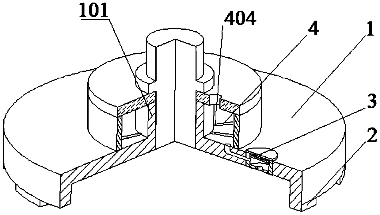
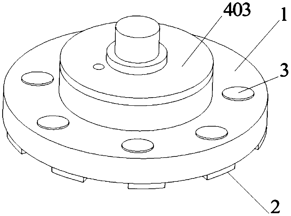
[0107]The invention discloses a grinding wheel with self-inner jet flow cooling, which comprises a grinding wheel main body 1 and a grinding part 2 . The grinding wheel main body 1 opens downward to form an inner cavity. The upper end of the grinding wheel main body 1 is provided with a connection part 101, and the connection part 101 is connected with the handle of the grinder. The grinding part 2 is provided on the bottom of the grinding wheel main body 1 . The grinding wheel also includes a spraying device 3 which is arranged on the top of the inner chamber of the grinding wheel main body 1 . The spraying device 3 includes: a spraying chamber 301 , a chamber pressurizing module 302 , a liquid inlet 303 , and a liquid spraying port 304 . The injection cavity 301 is a cavity structure, and is arranged on the top of the inner cavity of the grinding wheel main body 1 . The chamber pressure module 302 is disposed in the injection chamber 301 and located on the top of the inje...

Embodiment 2

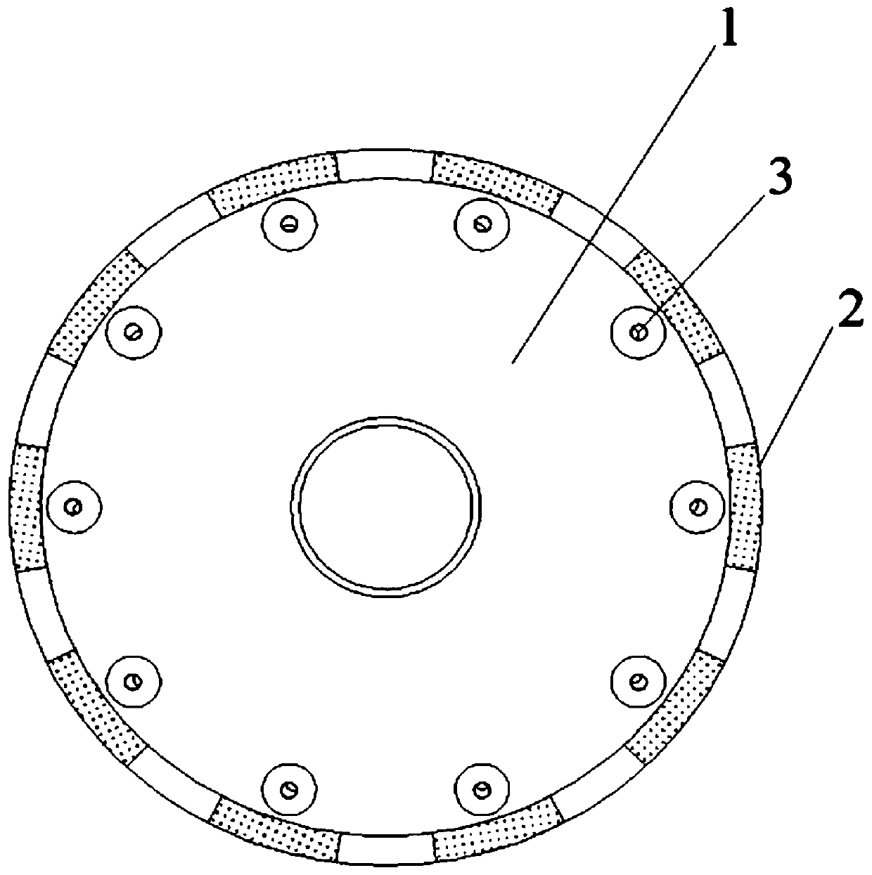
[0109] Embodiment 1 is repeated, except that a plurality of spraying devices 3 are arranged on the grinding wheel main body 1 . The spraying device 3 is evenly arranged on the top of the inner chamber of the grinding wheel main body 1 along the central axis of the grinding wheel main body 1 . The number of injection devices 3 is N. N is 10.

Embodiment 3

[0111] Embodiment 2 is repeated, except that the cavity pressure applying module 302 includes: a vibration generator 30201 and a compression component 30202 . The vibration generator 30201 is arranged on the top of the injection chamber 301, and the compression component 30202 is arranged on the bottom of the vibration generator 30201.


PUM


Abstract

The invention discloses an independent jet flow internal cooling grinding wheel. The grinding wheel comprises a grinding wheel body, and a grinding part; the grinding wheel body is opened downwards toform an inner cavity; a connecting part is arranged at the upper end of the grinding wheel body, the connecting part is connected with a cutter handle of a grinding machine, the grinding part is arranged on the bottom of the grinding wheel body, the grinding wheel further comprises a spraying device, the spraying device is arranged on the top of the inner cavity of the grinding wheel body and comprises a spraying cavity, a cavity pressure applying module, a liquid inlet, and a liquid spraying opening, the spraying cavity is of a cavity structure, and is arranged on the top of the inner cavityof the grinding wheel body, the cavity pressure applying module is arranged in the spraying cavity and is located on the top of the spraying cavity, the liquid inlet is formed in the spraying cavity,and communicates with a cooling liquid supply part, the liquid spraying opening is formed in the spraying cavity, the liquid spraying opening communicates with the inner cavity of the grinding wheelbody and the spraying cavity, the liquid spraying opening points to the grinding machining face, and cooling liquid is sprayed to the grinding machining face through the spraying opening. The problemsthat a traditional internal cooling type grinding wheel internal runner is difficult to machine, the machining cost is high, and the maximum spraying speed is limited are solved.

Description

technical field [0001] The invention relates to an internal cooling grinding wheel, in particular to an autonomous jet internal cooling grinding wheel, which belongs to the field of grinding processing. Background technique [0002] In machining, grinding is one of the most widely used material removal methods and belongs to finishing. [0003] During the grinding process, due to severe plastic deformation and friction, a large amount of grinding heat is generated in the grinding area between the grinding wheel and the workpiece. If the heat cannot be dissipated in time, burns and cracks will occur on the surface of the workpiece, which will seriously affect the workpiece. Processing quality. Traditionally, cooling is done by pouring coolant on the outside of the grinding wheel with nozzles. However, during the operation of the grinding wheel, a certain thickness of airflow layer is formed around it, which will prevent the external coolant from entering the grinding area, s...

Claims


Application Information

Patent Timeline
IPC IPC(8): B24D7/10
Inventor 彭锐涛吴艳萍刘开发童佳威唐新姿陈睿胡聪芳
Owner XIANGTAN UNIV
Why Eureka
Try Eureka