Packer rubber barrel die device and rubber barrel preparing method

A packer and rubber cartridge technology, which is applied in the field of seal manufacturing, can solve the problems of easy fracturing of the rubber cartridge, loss of the setting function of the rubber cartridge, and failure of the use of the packer, so as to achieve convenient processing, improve product quality, Reasonable effect of structural design

Pending Publication Date: 2019-06-07
SHANGHAI REAL SEALING TECH CO LTD
View PDF0 Cites 0 Cited by
  • Summary
  • Abstract
  • Description
  • Claims
  • Application Information

AI Technical Summary

Problems solved by technology

When the rubber sleeve is subjected to a high pressure difference in a high temperature environment, the rubber sleeve is easily fractured, causing the rubber sleeve to lose its setting function, resulting in the failure of the packer

Method used


Image

  • Packer rubber barrel die device and rubber barrel preparing method
  • Packer rubber barrel die device and rubber barrel preparing method
  • Packer rubber barrel die device and rubber barrel preparing method

Examples


Embodiment 1

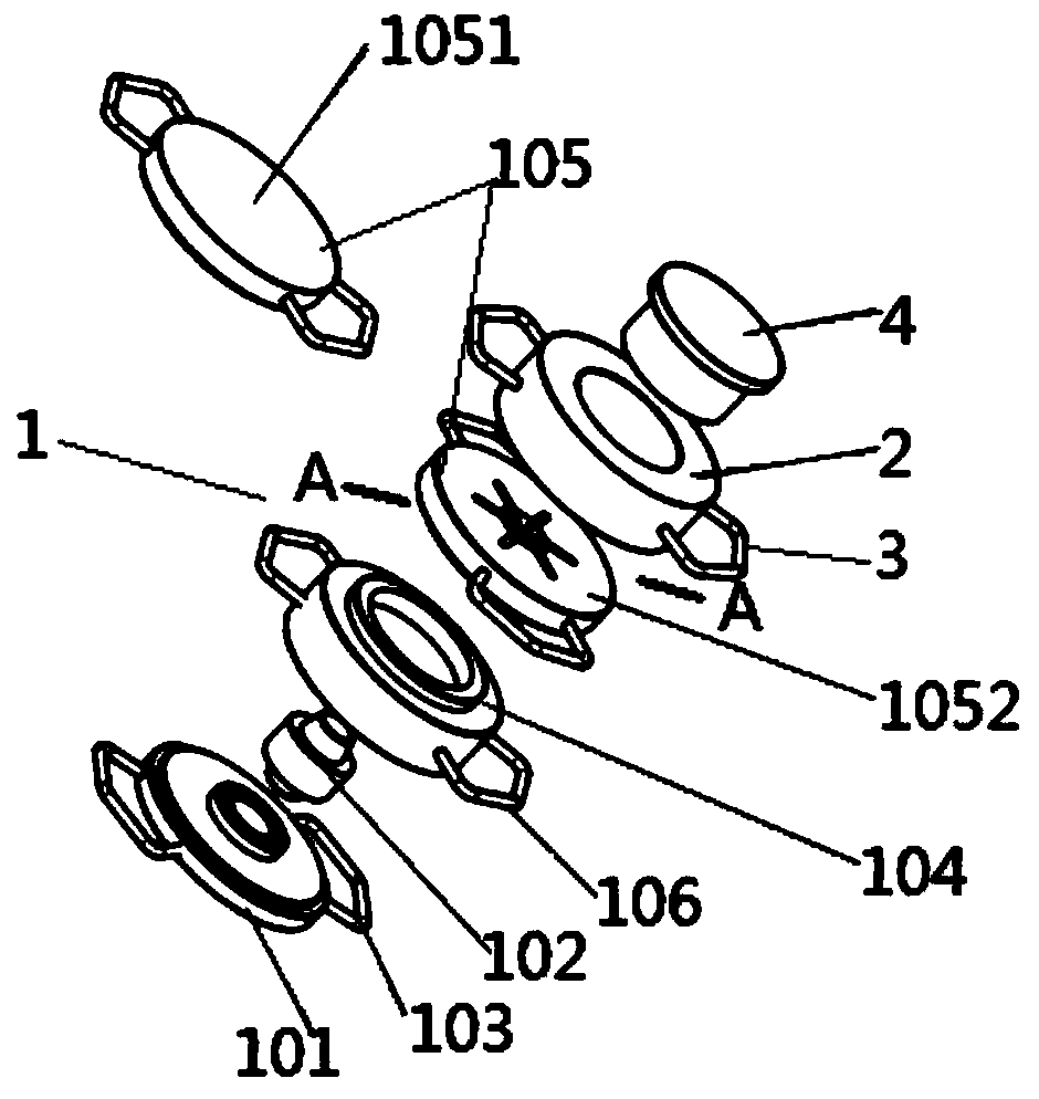
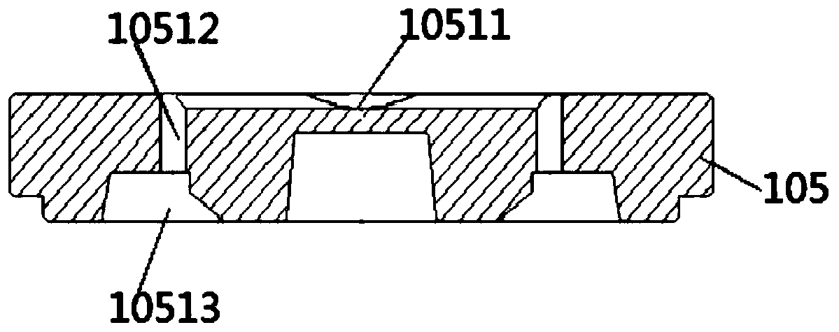
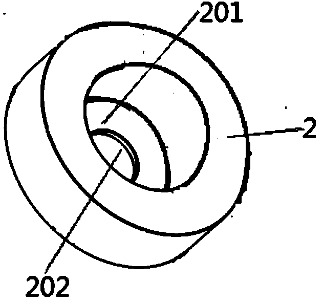
[0022] Such as Figure 1~Figure 3 A packer rubber cylinder mold device shown includes: a rubber cylinder forming mold 1, the upper part of the rubber cylinder forming mold 1 is provided with a rubber injection cylinder 2, and the rubber injection cylinder 2 is a hollow cylinder structure, the A pair of handles I3 are symmetrically connected to both sides of the injection cylinder 2, and a pressure injection head 4 is provided inside the injection cylinder 2, and the pressure injection head 4 can be freely separated from the injection cylinder 2, and the rubber cylinder forming mold 1 includes Lower formwork 101, mold core 102, handle II 103, middle formwork 104, upper formwork 105 and handle III 106, the upper part of the lower formwork 101 is connected to the lower end of the mold core 102, and a pair of handles II 103 are arranged symmetrically on both sides, and the mold core 102 is located in the middle Inside the formwork 104, the upper part of the middle formwork 104 is ...

Embodiment 2

[0031] Such as Figure 1~Figure 3 A packer rubber cylinder mold device shown includes: a rubber cylinder forming mold 1, the upper part of the rubber cylinder forming mold 1 is provided with a rubber injection cylinder 2, and the rubber injection cylinder 2 is a hollow cylinder structure, the A pair of handles I3 are symmetrically connected to both sides of the injection cylinder 2, and a pressure injection head 4 is provided inside the injection cylinder 2, and the pressure injection head 4 can be freely separated from the injection cylinder 2, and the rubber cylinder forming mold 1 includes Lower formwork 101, mold core 102, handle II 103, middle formwork 104, upper formwork 105 and handle III 106, the upper part of the lower formwork 101 is connected to the lower end of the mold core 102, and a pair of handles II 103 are arranged symmetrically on both sides, and the mold core 102 is located in the middle Inside the formwork 104, the upper part of the middle formwork 104 is ...


PUM


Abstract

The invention discloses a packer rubber barrel die device. A rubber barrel forming die is included. A glue injection barrel is arranged at the upper portion of the rubber barrel forming die and is ofa hollow cylinder structure. The two sides of the glue injection barrel are symmetrically connected with a pair of handles I. A pressing injection head is arranged in the glue injection barrel and canbe freely separated from the glue injection barrel. The packer rubber barrel die device is reasonable in structure design, and fusing and flowing distribution of sizing materials before the sizing materials flow into the die are optimized. Through the design of a flow guiding groove, the material temperature before the sizing materials enter a die cavity can be better increased, it is guaranteedthat the sizing materials injected into the die cavity can be sufficiently fused, and accordingly, radial and axial cracking risks during rubber barrel pressure bearing setting are reduced. It can beguaranteed that the die structure is simple and machining is convenient, and the rubber barrel product quality is improved as well.

Description

technical field [0001] The invention relates to the field of seal manufacturing, in particular to a packer rubber cylinder mold device and a rubber cylinder preparation method. Background technique [0002] Packer is a key tool for downhole oil production in oilfields, and is widely used in oilfield separate injection, layered reconstruction, fracturing, layered oil recovery, mechanical pipeline water plugging and other operational purposes. As the main component of the packer, the quality of the rubber cartridge directly affects the normal use effect and service life of the packer, and plays a decisive role in the use of the packer setting work. When the rubber sleeve is subjected to a high pressure difference in a high-temperature environment, the rubber sleeve is easily fractured, causing the rubber sleeve to lose its setting function, resulting in the failure of the packer. For the currently used high temperature and high pressure packer rubber cartridges, scientific an...

Claims


Application Information

Patent Timeline
Patent Type & Authority Applications(China)
IPC IPC(8): B29C33/00B29C35/02
Inventor 李恩军苟文亮李耿
Owner SHANGHAI REAL SEALING TECH CO LTD
Why Eureka
Try Eureka