Eureka AIR delivers breakthrough ideas for toughest innovation challenges, trusted by R&D personnel around the world.

Computer interlocking system

A computer interlocking and interlocking technology, applied in the computer field, can solve problems affecting the safety, reliability and usability of the interlocking system, interlocking data and software difficult to troubleshoot errors, inconvenient testing and safety certification, etc., to achieve safety And the effects of improving usability, overcoming control risk concentration, and reducing difficulty in engineering design and construction

Inactive Publication Date: 2019-06-07
BAOJI UNIV OF ARTS & SCI
View PDF7 Cites 10 Cited by
  • Summary
  • Abstract
  • Description
  • Claims
  • Application Information

AI Technical Summary

Problems solved by technology

[0003] However, the existing all-electronic computer interlocking system adopts a centralized control method, and all field devices are centrally controlled through the interlocking machine. The interlocking software is used to process these data sheets. Complex interlocking data and software are not only difficult to troubleshoot errors, but also inconvenient for testing and safety certification, which seriously affects the safety, reliability and usability of the interlocking system.
Moreover, if the interlocking mechanism of the centralized interlocking system fails, it will have a great impact on the system, and even cause the entire station to be paralyzed
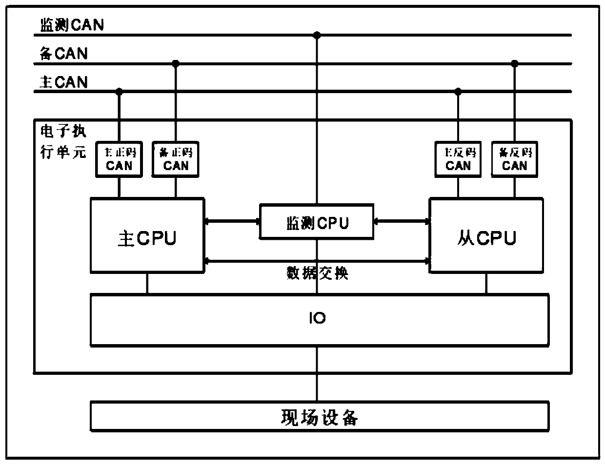
[0004] In addition, compared with typical computer interlocking systems, the communication nodes and communication data volume of all-electronic computer interlocking have increased, and the network load will also increase accordingly, which will affect the transmission rate of messages, so it will affect the system The real-time performance of communication has higher requirements, and the field bus, such as the commonly used CAN bus, has a low scheduling mechanism flexibility, and there will be message blocking when the network load is heavy, so the scheduling algorithm of the computer interlocking system needs Improve, reduce the probability of messages being discarded due to blocking, and improve the real-time performance of communication

Method used


Image

  • Computer interlocking system
  • Computer interlocking system
  • Computer interlocking system

Examples


Embodiment Construction

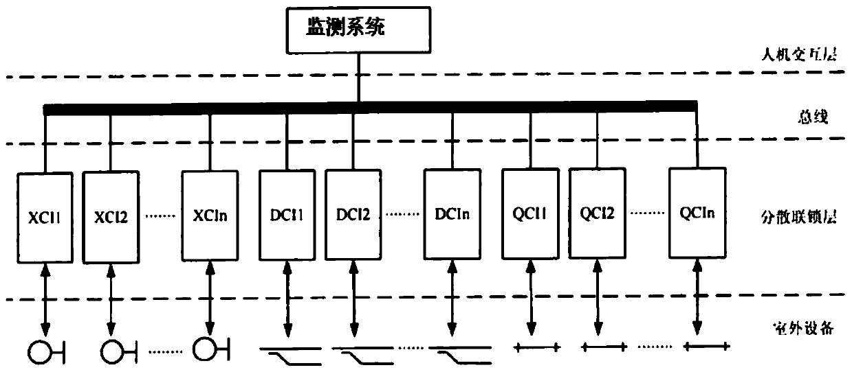
[0045] see figure 1 , a structural diagram of a computer interlocking system, comprising:

[0046] The human-computer interaction layer is used to realize the operation representation function;

[0047] The bus adopts a CAN bus communication network topology, an Ethernet communication network topology or a mixed networking topology of Ethernet and CAN bus. The bus communication protocol adopts a dynamic scheduling algorithm; each node in the network needs to share the resources of the system and needs to The network performs real-time scheduling in order to maximize the allocation of network resources to each node and improve bandwidth utilization, so that the messages of each node in the network can be reasonably scheduled. The dynamic scheduling algorithm schedules and allocates messages according to the real-time situation of the network. The system With higher flexibility and network utilization, this embodiment adopts the EDF dynamic scheduling method, and divides the re...


PUM


Abstract

The invention provides a computer interlocking system, comprising a human-computer interaction layer, a bus, a decentralized interlocking layer, a monitoring system and outdoor equipment. The bus adopts a CAN bus, Ethernet or the hybrid networking topology structure of the Ethernet and the CAN bus, and the bus communication protocol adopt a dynamic scheduling algorithm to schedule and distribute messages according to the real-time situation of the network; the decentralized interlocking layer is used for realizing the interlocking operation function, the decentralized interlocking layer is composed of basic interlocking units of signals, switches and sections corresponding to field equipment. The human-computer interaction layer is connected with the decentralized interlocking layer and the interior through a redundant wired communication network or the bus, and the decentralized interlocking layer is connected with the field equipment through an IO bus. The monitoring system includesa track module, a signal module, a turnout module, a semi-automatic block module, a field connection module and a scattered circuit module. The outdoor equipment includes an annunciator, a turnout anda track circuit. The computer interlocking system also comprises a maintenance monitoring subsystem containing a maintenance machine and a monitoring machine.

Description

technical field [0001] The invention relates to the computer field, in particular to a computer interlocking system. Background technique [0002] The computer interlocking system is to use computer control technology, computer communication and network technology to centrally judge the interlocking logic relationship of station signals, and realize the remote control of station signals, switches and routes in the dispatching area. It is the basic equipment to ensure the safe operation of trains. It is one of the more advanced interlocking systems at present. All-electronic computer interlocking is based on computer control technology, based on power electronic switch technology, and adopts advanced technologies such as computer communication and automatic detection to realize all electronic railway signal control computer interlocking equipment, all-electronic computer interlocking system It is mainly composed of interlocking cabinets, intelligent module cabinets and prote...

Claims


Application Information

Patent Timeline
IPC IPC(8): B61L7/08B61L27/00
Inventor 周新淳
Owner BAOJI UNIV OF ARTS & SCI
Why Eureka
Eureka Blog
Learn More