Measuring device special for architectural design
A technology for architectural design and measuring devices, applied in measuring devices, measuring instrument components, transportation and packaging, etc., can solve the problems of unadjustable brackets, troublesome measurement, inconvenient portability, etc., and achieve labor saving, strong practicability, and ingenious structure Effect
- Summary
- Abstract
- Description
- Claims
- Application Information
AI Technical Summary
Problems solved by technology
Method used
Image

Examples
Embodiment 1
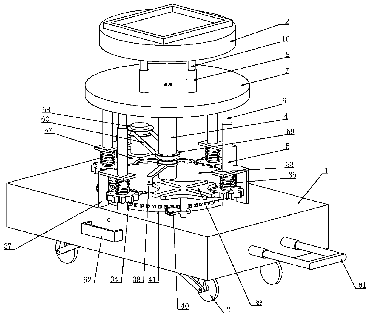
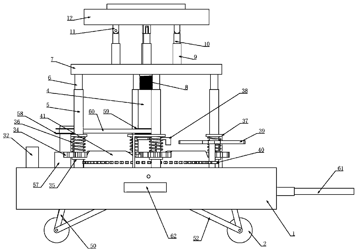
[0038] Embodiment one, combined with the attached Figure 1-18 , a special measuring device for architectural design, comprising a box 1 with an open lower end, the opening of the box 1 is facing downward, and it is characterized in that four sets of wheels 2 that can be retracted into the box 1 are provided at the lower end of the box 1, and the The wheels 2 are arranged in two rows of horizontal and vertical. The shrinking device is installed in the box 1, and the shrinking device of the box 1 is connected to the wheels 2, so that the wheels 2 are driven by the shrinking device to shrink into the box 1. The device connects the wheel 2 and the box body 1 together, and the specific structure of the shrinking device will be described in detail in the following embodiments, but the shrinking device can shrink the wheel 2 into the box body 1 to meet the requirements. When carrying, it can be The wheels 2 are retracted into the box body 1 through the shrinking device, which is eas...
Embodiment 2
[0043] Embodiment two, on the basis of embodiment one, in conjunction with the attached Figure 1-18 , the main shaft 4 is coaxially connected with a first gear 33, the circumference of the first gear 33 is uniformly meshed with the second gear 34, the radius of the first gear 33 is larger than the second gear 34, the second gear 34 is vertically coaxially slidably connected with the sleeve shaft 5 through the key, and the sleeve shaft 5 is provided with a key vertically, and a keyway is opened in the second gear 34, and the two cooperate to enable the second gear 34 to move vertically At the same time, it can also rotate with the sleeve shaft 5. The sleeve shaft 5 is coaxially connected with a ring 35, which can limit the vertical downward displacement of the second gear 34. Because the second gear 34 To be in the state of stable transmission, so add a circular ring 35 on the sleeve shaft 5, the second gear 34 is placed on the circular ring 35, to ensure the stability of its ...
Embodiment 3
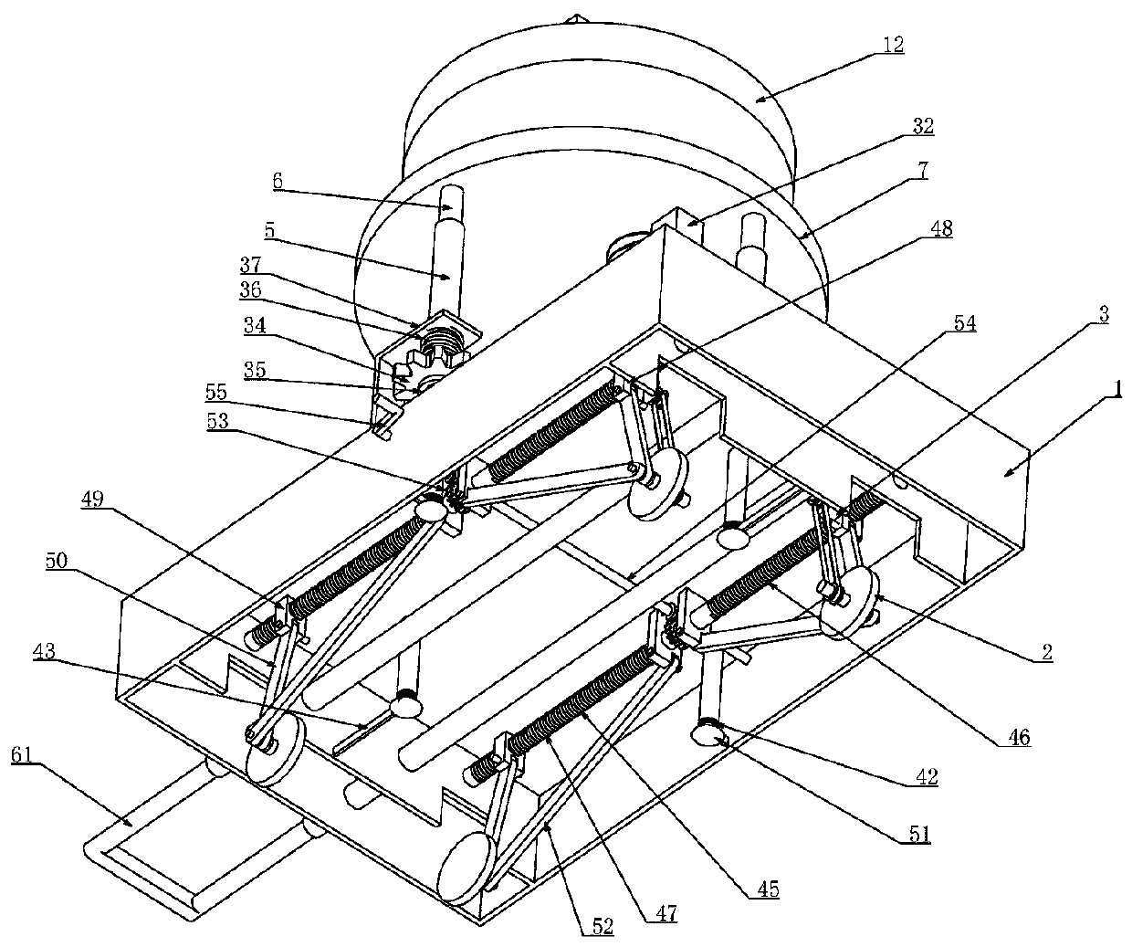
[0044] Embodiment three, on the basis of embodiment one or embodiment two, in combination with the attached Figure 1-18 The shrinking device includes two sets of two-way lead screws 45 that are vertically spaced in the box body 1 and connected to the box body 1 through lateral rotation. The two-way lead screws 45 are provided with first and opposite rotation directions from left to right. The external thread 46 and the second external thread 47, the non-threaded part in the middle of the two-way lead screw 45 is rotatably connected to the bearing seat 37 in the box body 1, and the first external thread 46 is threaded to fit a first slider 48, A second slider 49 is threaded on the second external thread 47, so that the first slider 48 and the second slider 49 can only move laterally along the two-way lead screw 45, because the first slider 48 and the second slider 49 They are all rectangular sliders. When setting, an inverted groove with a cross-section of "T" shape is provide...
PUM
 Abstract
Description
Claims
Application Information
 - Generate Ideas
- Intellectual Property
- Life Sciences
- Materials
- Tech Scout
- Unparalleled Data Quality
- Higher Quality Content
- 60% Fewer Hallucinations
Browse by: Latest US Patents, China's latest patents, Technical Efficacy Thesaurus, Application Domain, Technology Topic, Popular Technical Reports.
© 2025 PatSnap. All rights reserved.Legal|Privacy policy|Modern Slavery Act Transparency Statement|Sitemap|About US| Contact US: help@patsnap.com