
Detection and measurement of respiration using optical cameras and projected shadows

A breathing monitoring and projection technology, applied in the field of medical imaging, can solve the problems of error-prone, low image contrast, unusable, etc., and achieve the effect of reducing the complexity of data processing and improving the accuracy

Active Publication Date: 2022-07-29
KONINKLJIJKE PHILIPS NV
View PDF8 Cites 0 Cited by
  • Summary
  • Abstract
  • Description
  • Claims
  • Application Information

AI Technical Summary

Problems solved by technology

Difficulties with this approach include the placement of the camera, which typically views the patient unobstructed from above, and the complex image processing performed to extract chest motion
This method is also prone to errors due to small patient / camera misalignment, and / or due to low image contrast, e.g. if the patient is wearing an all-white hospital gown; and if the patient is lying in a supine position such that the chest cannot be viewed, and / or May not be available if the chest is covered by obscured components such as local radio frequency (RF) coils (as in some MR imaging procedures)

Method used


Image

  • Detection and measurement of respiration using optical cameras and projected shadows
  • Detection and measurement of respiration using optical cameras and projected shadows
  • Detection and measurement of respiration using optical cameras and projected shadows

Examples


Embodiment Construction

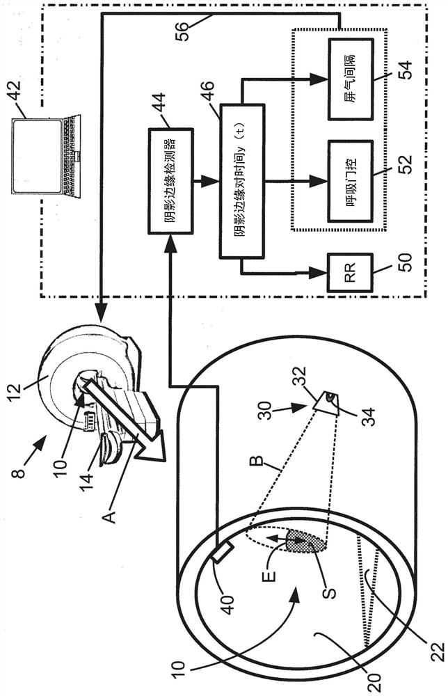
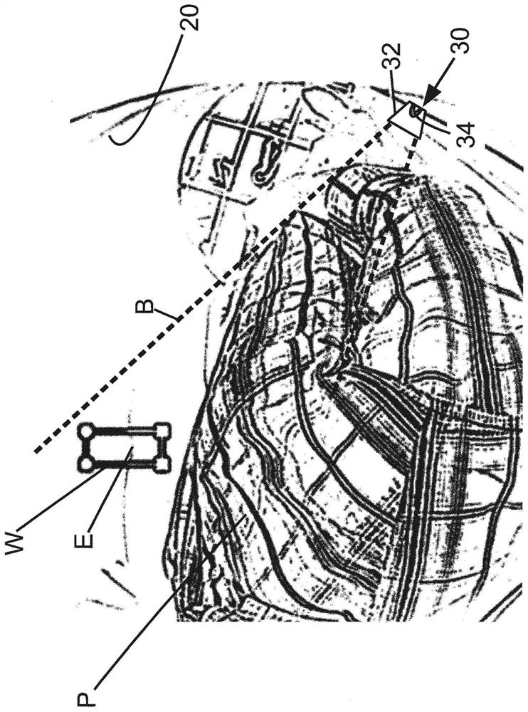
[0020] The camera-based respiration monitoring device disclosed herein is based on the insight made herein that it is possible to overcome existing camera-based concerns by capturing video of shadows of the chest projected onto a nearby surface, rather than directly imaging the patient's chest. Many difficulties with respiratory monitoring devices. Conveniently, in many medical imaging devices, the examination area is defined by the scanner bore, and the bore wall thus serves as a convenient surface onto which the shadow of the chest can be projected. For example, many magnetic resonance (MR) imaging devices employ a horizontal solenoid magnet and the examination region is located within the bore of the solenoid magnet. Likewise, many computed tomography (CT) imaging devices employ an X-ray source and an opposing X-ray detector assembly that rotates in unison around the patient, and the bore surrounds the examination area containing the patient to ensure patient safety with th...


PUM


Abstract

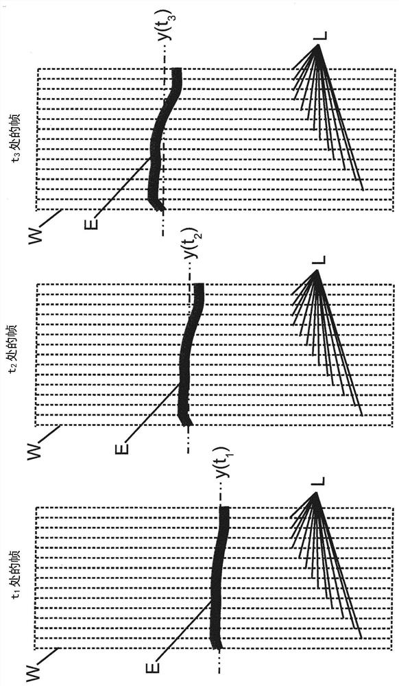
A respiration monitoring device comprising: a light source (30) arranged to generate a projected shadow (S) of an imaging object (P) positioned for imaging by an imaging device (8); a camera (40) arranged to acquire video of the projected shadow; and an electronic processor (42) programmed to extract the position of the edge of the projected shadow as a function of time from the acquired video. In some embodiments, the light source is arranged to project shadows onto the bore wall (20) of the imaging device, and the camera is arranged to capture video of the projected shadow on the bore wall. The electronic processor may be programmed to extract the position of the edge (E) as a one-dimensional function of time (46) based on the position of the edge in each frame of the acquired video and the timestamp of the video frame.

Description

technical field [0001] The following generally relates to the field of medical imaging, the field of respiratory monitoring, the field of respiratory-gated medical imaging, and related fields. Background technique [0002] Monitoring of patient breathing during medical imaging can serve a variety of useful purposes. The monitored breathing cycle can be used to perform prospective gated imaging, wherein imaging data is only collected during certain parts (ie phases) of the breathing cycle, which can reduce motion artifacts due to breathing. In an alternative retrospective gating method, imaging data is collected continuously and then binned by respiratory phase, and selected phases can be reconstructed. Respiration monitoring can also be used to detect breath holding, eg to trigger imaging when a patient holds his or her breath. Respiration monitoring can also serve patient safety monitoring functions, eg, an imaging session can be interrupted or terminated if breathing bec...

Claims


Application Information

Patent Timeline
Patent Type & Authority Patents(China)
IPC IPC(8): A61B5/00A61B5/08A61B5/113A61B5/11A61B6/00G01R33/565A61B6/03A61B5/055
CPCA61B5/7292A61B6/527A61B5/0033A61B5/0077A61B5/055A61B5/0816A61B5/1128A61B5/113G01R33/56509A61B6/032A61B6/037A61B6/541G01R33/283G01R33/5673
Inventor J·塞内加S·克吕格尔D·维尔茨V·让娜T·T·卡纳加萨巴帕蒂G·M·克斯滕
Owner KONINKLJIJKE PHILIPS NV
Learn More