
Torque spanner

A torque wrench and wrench head technology, applied in the field of torque wrenches, can solve the problems of violent destruction of nuts, low cost performance and high production cost, and achieve the effects of time-saving, labor-saving torque, strong practicability and convenient operation.

Inactive Publication Date: 2019-06-11
山东乐乐机械有限公司
View PDF0 Cites 12 Cited by
  • Summary
  • Abstract
  • Description
  • Claims
  • Application Information

AI Technical Summary

Problems solved by technology

[0002] The nut in the tool handle system is mainly used to cooperate with the handle body to act on the collet, so that the collet can clamp the tool; for the locking of the collet, problems often occur when using an ordinary wrench in actual production applications; because the torque value of the wrench cannot Fixed, if the locking force is not enough, the nut will not be tightly locked and easy to loosen, which will affect the assembly accuracy and dynamic balance of the handle collet, and even cause the tool to fall off; if the locking force is too large, it will cause violence to the nut destructive damage or even damage to the entire tool
The structure of the torque wrench currently on the market is too complicated and the production cost is too high, and ordinary users usually do not use it; moreover, most torque wrenches are monopolized by foreign companies, and the cost performance is low

Method used


Image

  • Torque spanner
  • Torque spanner

Examples


Embodiment Construction

[0010] The technical solution of the present invention is further illustrated below through specific examples.

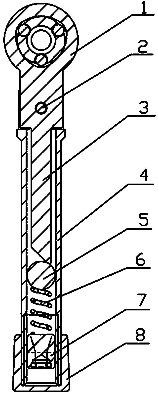
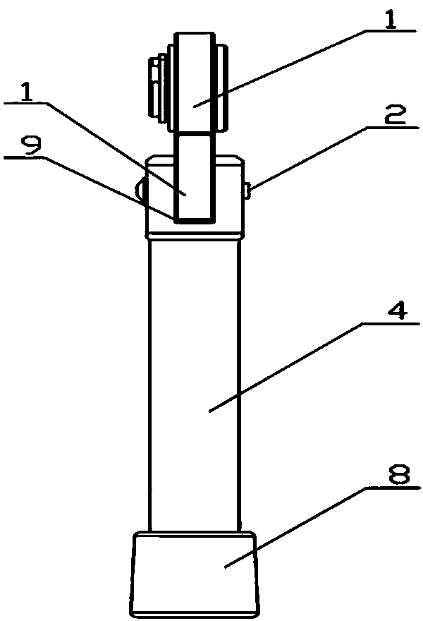
[0011] Such as Figure 1-2 Shown: a torque wrench, including a wrench head 1, a wrench rod 3 and a booster sleeve rod 4, the booster sleeve rod 4 is a hollow shell, the upper end is provided with a connecting groove 9, the wrench head 1 and the wrench rod 3 is the overall structure, the lower end of the wrench head 1 is provided with a boss, the connecting groove 9 of the wrench rod 3 is in contact with the convex table surface of the wrench head 1, the wrench rod 3 and the booster sleeve rod 4 are plug-in structures, And connected together through the rotating shaft 2. The steel ball 5 and the compression spring 6 are also arranged in the reinforcing sleeve rod 4. The lower end of the wrench rod 3 is provided with a beveled surface, and the beveled surface is in contact with the outer surface of the steel ball 5. The lower end of the steel ball 5 A compression spr...


PUM


Abstract

Disclosed is a torque spanner. The torque spanner comprises a spanner end, a spanner bar and a stress application loop bar. The stress application loop bar refers to a hollowed shell, and a connectinggroove is formed in the upper end of the stress application loop bar. The spanner end and the spanner bar are of an integrated structure. A boss is arranged at the necking position of the lower end of the spanner end. A connecting groove of the spanner bar abuts against the boss surface of the spanner end. The spanner bar and the stress application loop bar are movably connected together througha rotating shaft. A steel ball and a spring are further arranged inside the stress application loop bar. A diagonal plane is arranged at the lower end of the spanner bar and further abuts against theouter surface of the steel ball. The lower end of the steel ball is connected with the spring, and the lower end of the spring is connected with an adjusting jackscrew. The adjusting jackscrew is in threaded connection with the inner wall of the lower end of the stress application loop bar. The torque spanner is simple in structure, a nut can stretch into a bayonet inside the spanner end in the using process, the stress application loop bar is twisted, the steel ball can touch the inner wall of the stress application loop bar and a clear alarm can be raised when a set torque value is reached,vibrations can be felt on the stress application loop bar, and locking can be stopped at the moment. Operation is convenient, time and labor are saved and the torque can be adjusted.

Description

technical field [0001] The invention relates to a mechanical device, in particular to a torque wrench. Background technique [0002] The nut in the tool handle system is mainly used to cooperate with the handle body to act on the collet, so that the collet can clamp the tool; for the locking of the collet, problems often occur when using an ordinary wrench in actual production applications; because the torque value of the wrench cannot Fixed, if the locking force is not enough, the nut will not be tightly locked and easy to loosen, which will affect the assembly accuracy and dynamic balance of the handle collet, and even cause the tool to fall off; if the locking force is too large, it will cause violence to the nut Sexual damage or even damage to the entire tool. The structure of the torque wrench currently on the market is too complicated and the production cost is too high, and ordinary users usually do not use it; moreover, most torque wrenches are monopolized by foreig...

Claims


Application Information

Patent Timeline
Patent Type & Authority Applications(China)
IPC IPC(8): B25B13/48B25B23/142
Inventor 刘景
Owner 山东乐乐机械有限公司
Learn More