General induction quenching device for shafts and discs

A technology of induction hardening equipment and discs, which is applied in the direction of quenching equipment, heat treatment equipment, furnace types, etc., can solve the problems of complicated equipment implementation, overblown equipment, and complicated equipment settings, and achieve the effect of simple and easy quenching

Pending Publication Date: 2019-06-11
SHIYAN HENGJIN INDUCTION TECH CO LTD
View PDF0 Cites 2 Cited by
  • Summary
  • Abstract
  • Description
  • Claims
  • Application Information

AI Technical Summary

Problems solved by technology

However, for long-axis workpieces, this method will lead to a significant increase in the lifting stroke of the upper and lower centers, resulting in a super-high and bloated machine tool
[0004] The application number is: 2017213465203 provides an adjustable semi-automatic quenching device for automobile shafts. The device is relatively complicated to set up, especially the upper top (17) is adjusted and fixed by the support columns (4) on both sides, and the lower top (10) The bottom pressure spring (9) realizes elasticity, and the device is complicated to realize, and its versatility is limited at the same time

Method used


Image

  • General induction quenching device for shafts and discs
  • General induction quenching device for shafts and discs
  • General induction quenching device for shafts and discs

Examples


Embodiment Construction

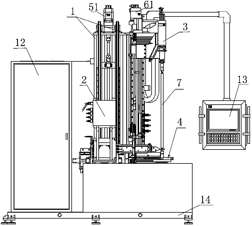
[0033] The present invention as Figure 1-5 shown.

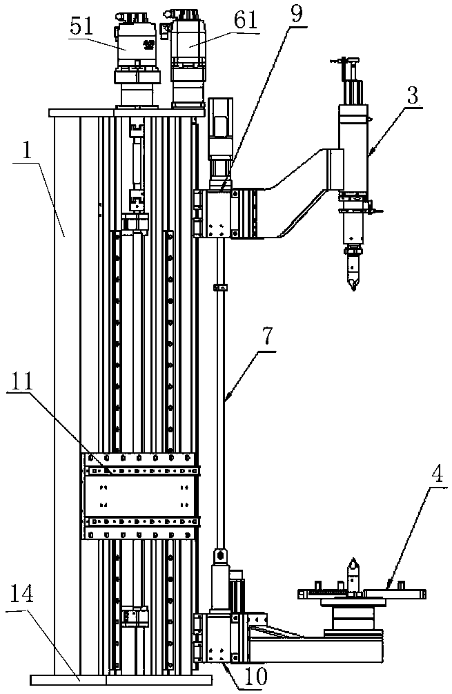
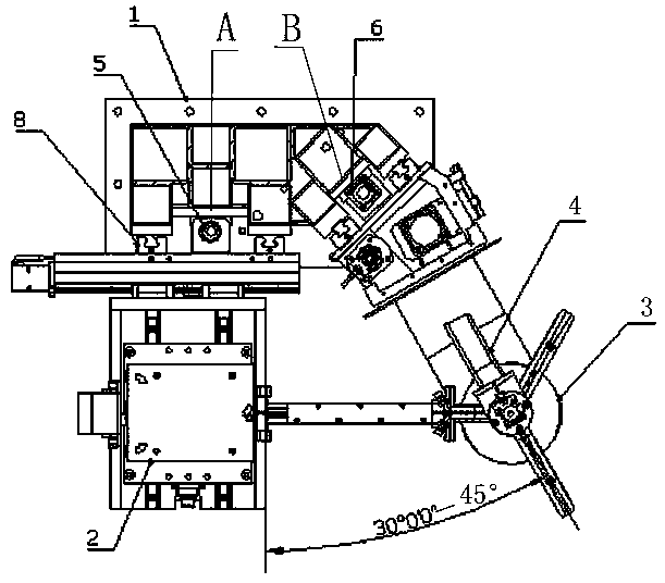
[0034] A common induction hardening equipment for shafts and discs, including a column structure 1, the column structure 1 is welded by steel, and welded on the base 14, and designed as two sides facing the direction of the station, wherein the two sides are clamped Angle structure setting, the first side A is vertically provided with a first guide rail body 8, a load slide 11 is provided through the first guide rail body 8, and a A ball screw 5, the top of the ball screw 5 is provided with a drive motor 51 for driving the load slide 11 to move up and down along the first guide rail body 8;

[0035] A ball screw 2 6 is provided between the upper top slide table 9 and the second guide rail body 81, and the top of the ball screw 2 6 is provided with a drive motor 2 61;

[0036] The base 14 is provided with a lower top slide 10, and the lower top 4 of the lower top slide 10 corresponds to the upper top 3, wherein the lower to...


PUM


Abstract

The invention discloses a general induction quenching device for shafts and discs. The two side faces are designed on the positions, facing the direction of the work station, of a standing column structure body, the two side faces are arranged in an included angle structure, a first guiding rail body and a first ball screw are used to drive a loading sliding table so that the quenching load movesup and down, and a second guiding rail body and a second ball screw are used to drive top and lower tips to move relatively. The upper and lower tips can achieve the clamping of the shaft-like workpieces of different lengths, meanwhile, the up and down movement of the quenching load can achieve the non movement of the shaft-like components, and the quenching of the long-shaft-like components is simple and easy to operate accordingly; and the manner that the quenching load shares the same standing column with the upper and lower tips is adopted, the difficulty of the manufacturing and installation is reduced, the accuracy of the equipment is improved, and the appearance size of the machine tool is reduced, so that the machine tool is more exquisite and beautiful.

Description

technical field [0001] The invention relates to quenching equipment, which is specially used for induction heat treatment and quenching equipment of shafts and disks, in particular to induction quenching equipment for shafts and disks. Background technique [0002] The purpose of quenching is to use supercooled austenite to transform martensite or bainite to obtain martensite or bainite structure, and then cooperate with tempering at different temperatures to greatly improve the rigidity, hardness, and wear resistance of the steel. properties, fatigue strength and toughness, etc., so as to meet the different needs of various mechanical parts and tools. It can also meet the special physical and chemical properties of special steel such as ferromagnetism and corrosion resistance through quenching. [0003] Shaft and disk parts are widely used in automobiles and construction machinery, and the production and processing requirements of the parts are also very high. The traditi...

Claims


Application Information

Patent Timeline
IPC IPC(8): C21D9/28C21D9/00C21D1/10C21D1/62
CPCY02P10/25
Inventor 周祥成万美华张明星
Owner SHIYAN HENGJIN INDUCTION TECH CO LTD
Why Eureka
Try Eureka