Combined annular mist flow phase-splitting flow measuring method

A flow measurement, combined technology, applied in the direction of detecting the dynamic effect of fluid flow, volume/mass flow generated by electromagnetic effect, volume/mass flow generated by mechanical effect, etc., can solve the problem that cannot fully meet the measurement of annular mist flow requirements, no annular mist liquid film, lack of pertinence, etc.

Active Publication Date: 2019-06-11
TIANJIN UNIV
View PDF7 Cites 8 Cited by
  • Summary
  • Abstract
  • Description
  • Claims
  • Application Information

AI Technical Summary

Problems solved by technology

In order to reduce the error of the vortex flowmeter when it is used to measure the flow rate of the annular mist flow, researchers have carried out a lot of exploration. Small error[2][3][4], however, this method lacks a theoretical basis and can only be used empirically under specific working conditions
Afterwards, a large number of combined instrument schemes based on vortex flowmeters were proposed, such as the combination of double vortex [5], the combination of vortex and target flowmeter [6], the combination of vortex and orifice [7] ], vortex street and V-cone combination[8][9], etc. These schemes use the signals obtained from different flowmeters, combined with relevant theories and empirical equations, to deduce the two-phase flow or dryness, but in these schemes In all of them, it is based on the fitting dependence between the inlet conditions and the flow meter signal, and there is no theoretical support for the annular mist flow liquid film and droplet entrainment, so the wide applicability is still not guaranteed.
This is also determined by the limitations of traditional flow meters. Traditional flow meters are designed for single-phase fluid measurement. They pay more attention to reliability and versatility, and lack pertinence. Combining them cannot fully meet the requirements of annular mist flow. measurement requirements

Method used


Image

  • Combined annular mist flow phase-splitting flow measuring method
  • Combined annular mist flow phase-splitting flow measuring method
  • Combined annular mist flow phase-splitting flow measuring method

Examples


Embodiment Construction

[0042] In order to further understand the features, technical means, and specific objectives and functions achieved by the present invention, the specific embodiments of the present invention will be described in detail below in conjunction with the accompanying drawings.

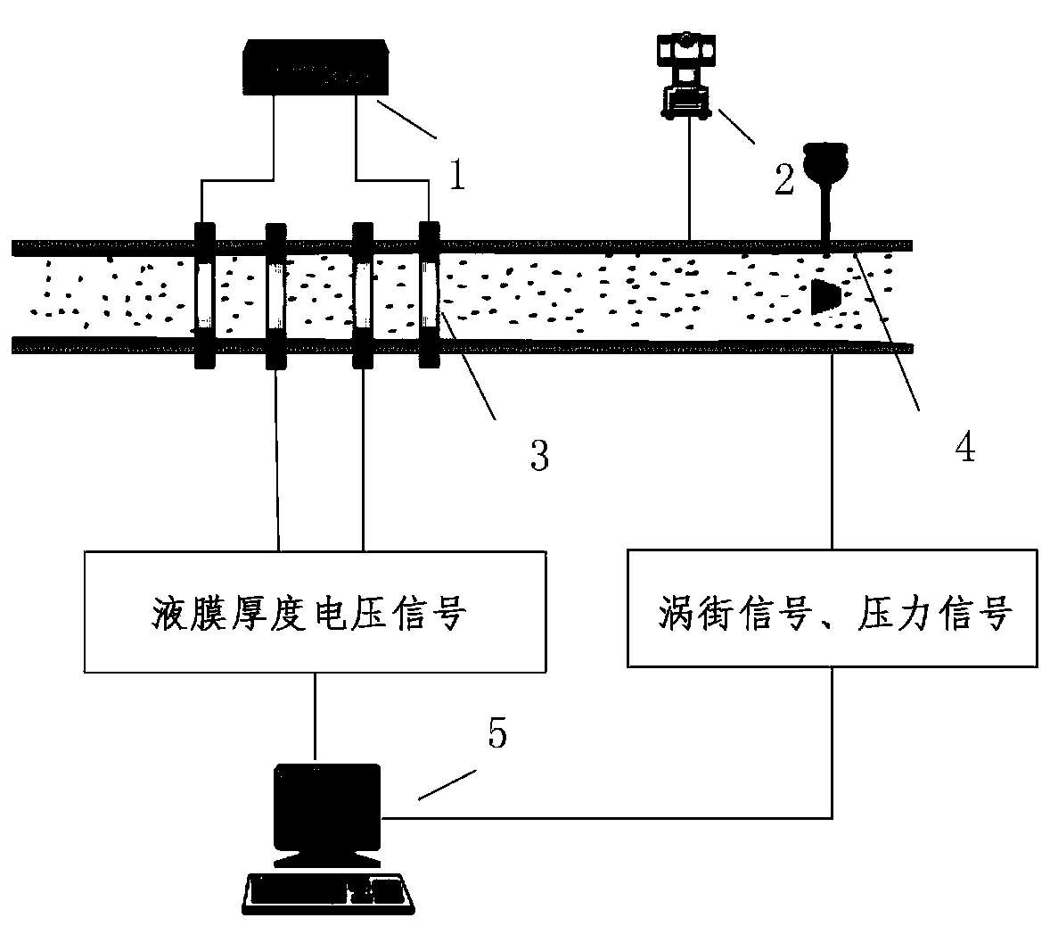
[0043] Measurement process of the present invention passes through following structure (see figure 1 ) Realization: 1 AC excitation power supply, 3 annular conductance sensor, 4 vortex street sensor, 2 pressure sensor and 5 industrial computer. The AC excitation power supply provides carrier signals for the ring electrodes, drives the ring electrodes to generate voltage signals, and converts the liquid film thickness information into voltage. The vortex sensor is used to measure the gas phase flow containing liquid droplets, and the pressure sensor is used to measure the real-time pressure P in the pipeline.

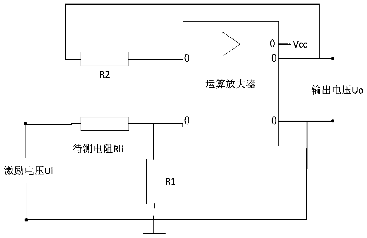
[0044] The conductance sensor that the present invention adopts adopts direct voltage excitation,...


PUM


Abstract

The invention relates to a combined annular mist flow phase-splitting flow measuring method. The combined annular mist flow phase-splitting flow measuring method comprises the following steps: measuring an average liquid membrane thickness of an annular mist flow in real time by using two pairs of electric conductive annular wall-attached sensors; performing relevant analysis on signals measured by the two pairs of front and back annular electric conductive sensors according to a relevant speed measuring method to obtain an average liquid membrane interface flow rate, and solving a mass flow of a liquid membrane according to the average liquid membrane thickness and the liquid membrane interface flow rate; acquiring gaseous phase density by using a vortex sensor; obtaining a read gaseous phase flow through calculation; and using the measured liquid membrane flow, the read gaseous phase flow rate and the read gaseous phase flow as known quantities, performing the iterative solution on an entrainment rate E and a reading coefficient OR by using a formula until the entrainment rate is converged, and finally calculating a total liquid phase flow according to the entrainment rate, so that the measurement objective of the annular mist flow phase-splitting flow can be achieved.

Description

technical field [0001] The invention belongs to the field of parameter measurement of gas-liquid two-phase flow, and relates to a phase-separated flow measurement technology of annular mist flow, which can be used for measuring gas-liquid phase-separated flow of annular mist flow in industrial applications. Background technique [0002] Moisture is a two-phase flow pattern in which the gas (vapor) phase is the continuous phase and the liquid phase is the discrete phase. When the flow rate is high, it appears as a mist flow, and the core of the air flow is a mixture of air flow and liquid droplets. As an important two-phase flow pattern, mist flow exists widely in industrial fields, such as vaporization devices such as boilers and nuclear reactor steam generators, pipelines for oil and natural gas, chemical equipment such as various evaporators, condensers, and reactors, and gas-liquid Mixers, heat exchangers, fire extinguishers, various engine combustion chambers and underwa...

Claims


Application Information

Patent Timeline
Patent Type & Authority Applications(China)
IPC IPC(8): G01F1/56G01F1/32
Inventor 孙宏军张文强桂明洋
Owner TIANJIN UNIV
Why Eureka
Try Eureka