High-speed motion target deformation measurement system and method based on DMD

A technology of high-speed movement and measurement system, applied in measurement devices, instruments, optical devices, etc., can solve the problems of inability to measure moving workpieces, limited application, slow measurement speed, etc.

Active Publication Date: 2019-01-04
BEIJING INSTITUTE OF TECHNOLOGYGY
View PDF10 Cites 6 Cited by
  • Summary
  • Abstract
  • Description
  • Claims
  • Application Information

AI Technical Summary

Problems solved by technology

Common measurement methods include contact measurement and non-contact measurement. Although the traditional contact measurement method has strong versatility (no special requirements for the material and color of the measured object), high precision (usually up to micron level), Effective and reliable, etc., have been widely used in advanced manufacturing and scientific research, but there are also inherent limitations, such as: the contact between the probe and the surface of the workpiece is easy to cause scratches on the surface of high-precision devices, and it is impossible to measure the moving workpiece; The small vibration of the material, the softness and hardness of the material, etc. will cause measurement error problems; the shortcomings of slow measurement speed, high environmental requirements, and high cost limit its application in the field of rapid measurement.

Method used


Image

  • High-speed motion target deformation measurement system and method based on DMD
  • High-speed motion target deformation measurement system and method based on DMD
  • High-speed motion target deformation measurement system and method based on DMD

Examples


Embodiment 1

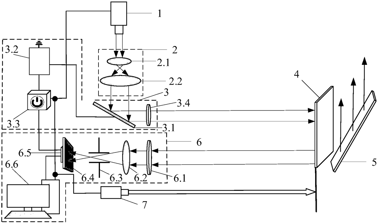
[0091] Such as figure 1 , This is a DMD-based high-speed moving target deformation measurement system disclosed in the embodiment, which includes a DMD scanning first-level subsystem 3 and a receiving and detecting first-level subsystem 6, a laser 1, a collimating beam expander module 2, and a laser rangefinder 7. Projection screen 4, reflector 5. The DMD scanning first-level subsystem 3 is used to provide uniform illumination in the field of view in the calibration experiment and to generate simulated high-speed moving targets in the measurement simulation high-speed target experiment. The receiving and detecting sub-system 6 is used to receive the deformation signal of the high-speed moving target, and convert the target deformation information into the pixel change amount on the detector 6.5. The laser 1 is used to emit the laser beam; the collimating beam expansion module 2 is used to collimate the laser beam emitted by the laser 1 and expand the beam to the DMD scanning f...


PUM


Abstract

The present invention discloses a high-speed motion target deformation measurement system and method based on DMD, and belongs to the technical field of high-speed motion target deformation measurement. The system comprises a laser, a collimation and beam expanding module, a DMD scanning first-grade sub system, a projection screen, a reflection plate, a receiving detection first-grade sub system and a laser distance measuring instrument; and the DMD is employed to simulate a high-speed motion target with an unchanged position through adoption of a modulation pattern high-frequency loading mode, the optical path structure and parameters are fixed through adoption of a mode of system calibration and deformation measurement of the high-speed motion target with an unchanged simulation position, and a linear array CCD sampling frequency is employed to coordinate with the DMD frequency to achieve the target size intensity-pixel collection to achieve the data collection of the external physical deformation quantity of the high-speed motion target. The present invention further discloses a target deformation measurement method based on the system. The high-speed motion target deformation measurement system and method based on DMD can achieve the non-contact accurate measurement of the external physical deformation quantity of the high-speed motion target, and are high in measurement precision and fast in time.

Description

Technical field [0001] The invention belongs to the technical field of high-speed moving target deformation measurement, and particularly relates to a DMD-based high-speed moving target deformation measurement system and method. Background technique [0002] In recent years, as the country's industrialization level continues to rise, the field of precision engineering measurement requires a high-level evaluation system with the advantages of large measurement range, high accuracy, and good dynamic measurement characteristics. Precision / ultra-precision processing technology has become the main development direction and important research field of advanced processing and manufacturing technology. It integrates the latest scientific and technological achievements in different disciplines such as mechanical technology, measurement technology, modern electronic technology and computer technology. Applications in high-tech fields such as medicine, communications, and microelectronics a...

Claims


Application Information

Patent Timeline
Patent Type & Authority Applications(China)
IPC IPC(8): G01B11/16G01B11/00
CPCG01B11/00G01B11/167
Inventor 郝群曹杰徐成强王营博徐辰宇
Owner BEIJING INSTITUTE OF TECHNOLOGYGY
Why Eureka
Try Eureka