Device and method for counting micro-particles based on micro-nanofiber

A micro-nano fiber and micro-particle technology, applied in electromagnetic wave transmission systems, electrical components, transmission systems, etc., to meet special requirements, large dynamic range, and achieve the effect of sensitivity

Inactive Publication Date: 2013-01-09
NAT UNIV OF DEFENSE TECH
View PDF2 Cites 6 Cited by
  • Summary
  • Abstract
  • Description
  • Claims
  • Application Information

AI Technical Summary

Problems solved by technology

[0008] In order to solve the technical problems encountered in the monitoring of pollutants in the current vacuum system, the present invention provides a micro-particle counting device based on micro-nano optical fiber that can accurately and effectively detect pollutants

Method used


Image

  • Device and method for counting micro-particles based on micro-nanofiber
  • Device and method for counting micro-particles based on micro-nanofiber

Examples


Embodiment Construction

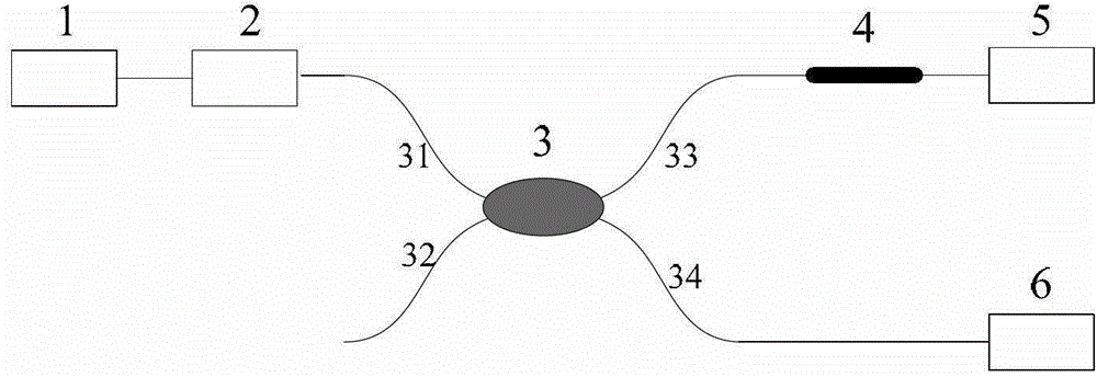
[0026] see figure 1 The device in this embodiment includes a narrow linewidth laser 1, a fiber isolator 2 with an isolation greater than 30 dB, a fiber coupler 3 with a coupling mode of 2×2, a micro-nano fiber 4, a signal light detector 5 and a reference light detector 6 . Wherein the narrow linewidth laser 1 is used to eliminate the selectivity of the beam splitting ratio of the coupler to the wavelength. The output light of the narrow-linewidth laser 1 is injected into the isolator 2, and then divided into two beams of light through the first port 31 of the fiber coupler 3, respectively from the third port 33 of the fiber coupler 3 and the fourth port of the fiber coupler 3 34 output, wherein the light of the third port 33 of the fiber coupler 3 passes through the micro-nano fiber 4 as signal light and is monitored by the detector 5, and the light of the fourth port 34 of the fiber coupler 3 is used as a reference light by the reference A light detector 6 monitors the ligh...


PUM

PropertyMeasurementUnit
Diameteraaaaaaaaaa

Abstract

The invention discloses a device and a method for counting micro-particles based on a micro-nanofiber. The device comprises a narrow linewidth laser, a fiber isolator, a fiber coupler, the micro-nanofiber, a signal light detector and a reference light detector, the coupled mode of the fiber coupler is 2X2, an output end of the laser is connected to the fiber isolator through a fiber and then connected to a first port of the fiber coupler, the signal light detector is connected with the micro-nanofiber and then connected to a third port of the fiber coupler, and the reference light detector is connected to a fourth port of the fiber coupler through a fiber. The device has the advantages that micron-diameter particles are sensed by the aid of large evanescent field of the micro-nanofiber, owing to high light confinement capacity and guide capacity of the micro-nanofiber, the shortcomings of scattered beam energy and difficulty in gathering and detecting scattered light of a traditional optical method are overcome, and difficulty in realizing high stability and resonance frequency of resonant quality sensing is avoided in principle.

Description

technical field [0001] The invention relates to a device and method for counting microparticles based on micronano optical fibers. Background technique [0002] Microparticle sensing technology has an urgent application demand in systems that require clean control, such as chemical macromolecular detection, semiconductor technology, and high-throughput laser systems. The National Ignition Facility Project (National Ignition Facility Project, referred to as NIF, which provides laser ignition for nuclear fusion) has established a "clean control protocol (CCP)" for optical components involving high luminous flux and the surrounding environment, and the manufacturing, cleaning and installation of core components And the materials are strictly regulated to ensure that the laser system has as little residual pollutants as possible during the manufacturing and installation process, and produces as little pollutants as possible during use. To achieve the final ignition goal of the ...

Claims


Application Information

Patent Timeline
IPC IPC(8): H04B10/071
Inventor 宋章启卫正统张学亮阳明晔陈宇中孟州
Owner NAT UNIV OF DEFENSE TECH
Why Eureka
Try Eureka