Planar error detection system

A technology of error system and plane detection, applied in the direction of measuring devices, instruments, optical devices, etc., can solve the problem of low measurement accuracy of surface roughness, and achieve the effect of high measurement accuracy

Inactive Publication Date: 2010-11-10
UNIV OF SHANGHAI FOR SCI & TECH
View PDF4 Cites 6 Cited by
  • Summary
  • Abstract
  • Description
  • Claims
  • Application Information

AI Technical Summary

Problems solved by technology

[0003] The present invention is aimed at the problem that the measurement accuracy of the surface roughness is not high, and proposes a detection plane error system, which uses the color displacement principle of the optical imaging system to perform non-contact plane error detection

Method used


Image

  • Planar error detection system
  • Planar error detection system

Examples


Embodiment Construction

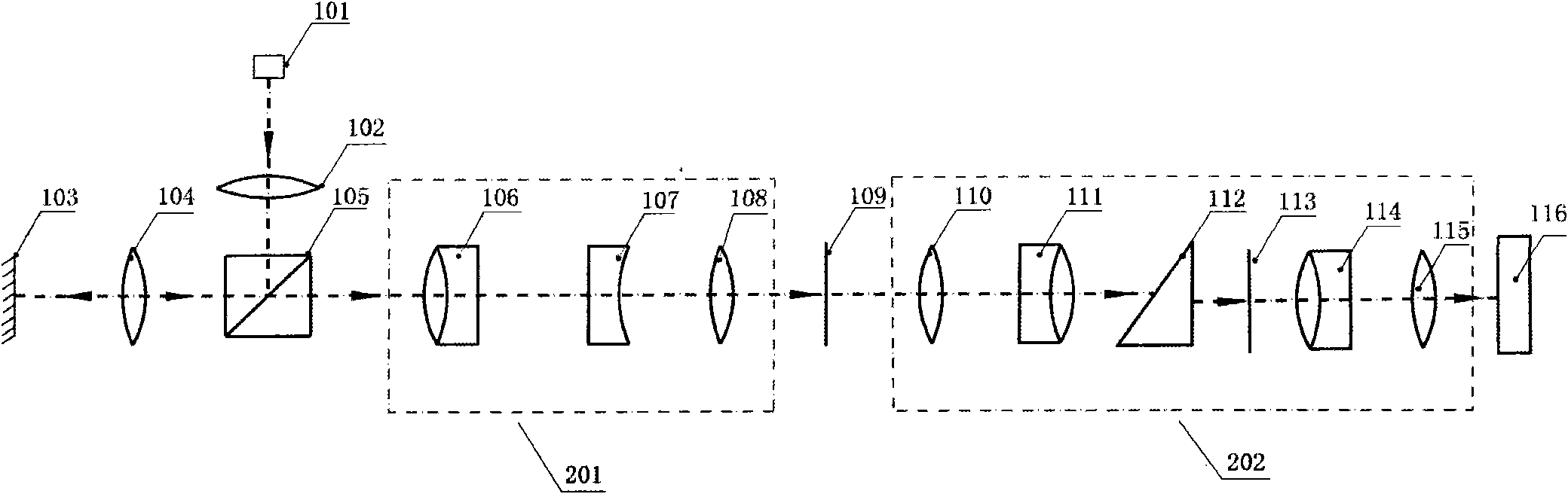
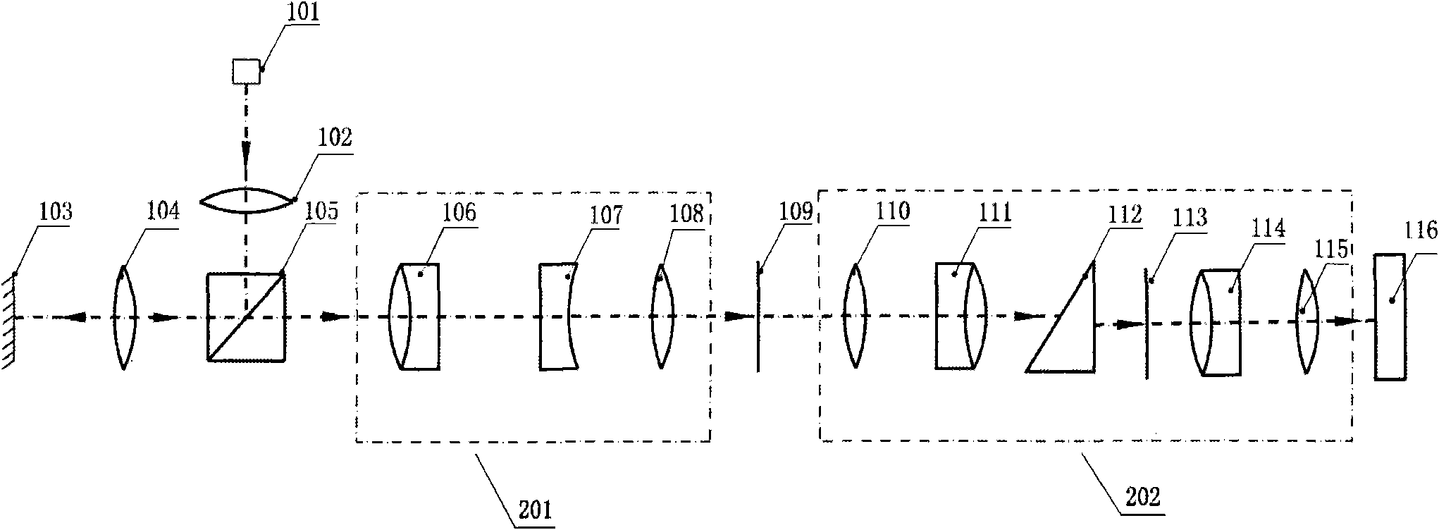
[0010] The optical system proposed by the present invention is a confocal system. Such as figure 1 The schematic diagram of the optical structure of the detection plane error system shown, the system includes an illumination system, an imaging system and a wavelength identification system. The illumination system includes a white light source 101 , an illumination optical system 102 and a half mirror 105 . The imaging system includes an infinity objective lens 104 , a chromatic aberration generating system 201 and a slit 109 . The wavelength identification system includes a spectroscopic optical system 202 and an area array image sensor CCD116. Wherein, the infinity-type objective lens 104 is a kind of infinity-type achromatic objective lens; the chromatic aberration generation system 201 is made up of three groups of lenses 106, 107 and 108; 111 and 114, plus wedge prism 112 and diffraction grating 113 are combined.

[0011] The illumination beam emitted from the white li...


PUM


Abstract

The invention relates to a planar error detection system. Illumination light beams sent by a white light source pass through an illumination optical system, emergent parallel light passes through a half transparent and half reflecting mirror and an afocal object lens to be focalized on a detected object, light reflected by the detected object enters a color difference generation system, light with different wave lengths has different focuses for the same optical system and thus corresponds to different image distances, and only the light with the corresponding wave length can be allowed to pass through a slit because of the confocal principle. The light with the corresponding wave length is imaged on special positions of a face array image sensor through a light splitting optical system, and image signals in special positions of the image sensor are sent into a computer to be converted into corresponding wave length signals. A confocal light path is adopted, and an ordinary white light source is adopted. Compared with other methods adopting a single-color laser light source, the invention has the advantages of practical and popularization value and high measuring precision, can reach the nanometer level precision through computer analog simulation, and can realize real-time on-line roughness detection.

Description

technical field [0001] The invention relates to a detection device, in particular to a system for detecting plane errors. Background technique [0002] Surface roughness measurement methods can be divided into contact measurement and non-contact measurement. The traditional method of tactile measurement is to use a profilometer. The stylus is used to measure along the surface to obtain the surface profile. Although profilometers provide good results, the probes often damage the surface being tested. In addition, roughness data is easily affected by the radius of the probe measurement. Non-contact measurement, especially optical measurement, has the advantages of non-contact, no damage to the surface, high precision and fast response in the measurement of surface roughness. It has become the main development direction in surface roughness measurement technology. The rapid development of non-contact measurement includes not only direct measurement methods such as atomic f...

Claims


Application Information

Patent Timeline
Patent Type & Authority Applications(China)
IPC IPC(8): G01B11/30
Inventor 李湘宁李楚元吴宇昊
Owner UNIV OF SHANGHAI FOR SCI & TECH
Why Eureka
Try Eureka