Battery monitoring method and system

A battery monitoring and battery technology, applied in the direction of measuring electricity, measuring electrical variables, measuring devices, etc., can solve the problems of low safety and poor accuracy of monitoring data, and achieve the effect of improving safety, improving accuracy, and not being easy to short circuit

Active Publication Date: 2019-06-11
AULTON NEW ENERGY AUTOMOTIVE TECHNOLOGY GROUP +1
View PDF19 Cites 9 Cited by
  • Summary
  • Abstract
  • Description
  • Claims
  • Application Information

AI Technical Summary

Problems solved by technology

[0003] The technical problem to be solved by the present invention is to provide a battery monitoring method and system in order to overcome the defects of poor accuracy and low safety of monitoring data of lithium power batteries in the prior art

Method used


Image

  • Battery monitoring method and system
  • Battery monitoring method and system

Examples


Embodiment 1

[0044] This embodiment provides a battery monitoring method. In this embodiment, the battery is a lithium power battery used in new energy vehicles, but the battery type is not specifically limited, and different types of batteries can be monitored according to actual conditions. .

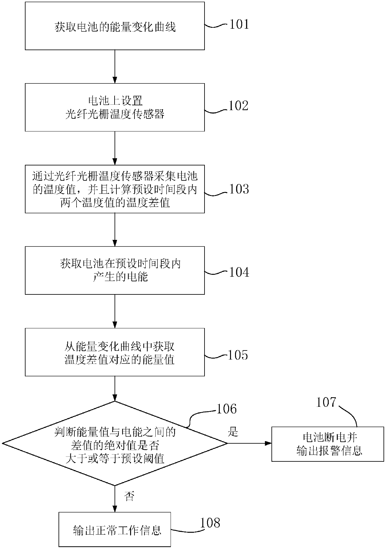
[0045] Such as figure 1 As shown, the battery monitoring method includes the following steps:

[0046] Step 101, acquiring the energy change curve of the battery.

[0047] In this step, the energy change curve of the battery is acquired and stored in advance, the energy change curve is used to characterize the energy change of the battery when charging or discharging in an ideal state, and each energy value of the energy change curve is related to There is a one-to-one correspondence between a temperature difference of the battery.

[0048] Step 102, installing a fiber grating temperature sensor on the battery.

[0049] In this embodiment, the battery includes several battery cells, and the nu...

Embodiment 2

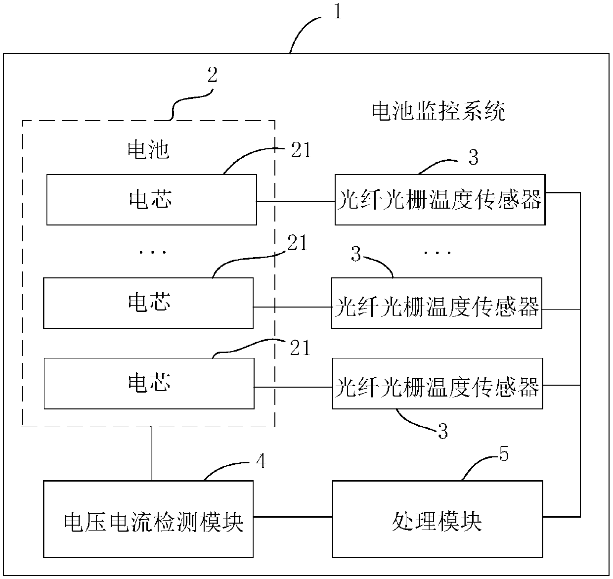
[0068] This embodiment provides a battery monitoring system. In this embodiment, the battery is a lithium power battery used in new energy vehicles, but the battery type is not specifically limited, and different types of batteries can be monitored according to actual conditions. .

[0069] Such as figure 2 As shown, the battery monitoring system 1 includes a battery 2, a number of fiber grating temperature sensors 3, a voltage and current detection module 4 and a processing module 5, and the battery 2 includes a number of battery cells 21. In this embodiment, the battery cells are not specifically limited. and the number of fiber grating temperature sensors can be determined according to the actual situation.

[0070] A plurality of fiber grating temperature sensors are installed on the electrode positions on the surface of each cell, and the accuracy of the test data can be improved by setting the fiber grating temperature sensors on the electrode positions on the surface ...


PUM


Abstract

The invention discloses a battery monitoring method and system. The battery monitoring method comprises the following steps of obtaining an energy change curve of a battery, wherein the energy changecurve represents an energy change of the battery during charging or discharging under an ideal state, each energy value of the energy change curve corresponds to one temperature difference value of the battery, and a fiber bragg grating temperature sensor is arranged on the battery; acquiring temperature values of the battery during the charging or discharging through the fiber bragg grating temperature sensor, and calculating a first temperature difference value between two temperature values of the battery in a preset time period; obtaining first electric energy, charged or discharged in thepreset time period, of the battery; and obtaining a first energy value corresponding to the first temperature difference value from the energy change curve, judging whether an absolute value of a difference value between the first energy value and the first electric energy is greater than or equal to a first preset threshold value or not, and if the absolute value of the difference value is greater than or equal to the first preset threshold value, ending power supply of the battery and outputting alarm information. The method and system are capable of improving the correctness of battery monitoring data and improving the safety of batteries during the work.

Description

technical field [0001] The invention relates to the field of battery monitoring, in particular to a monitoring method and system for a lithium power battery. Background technique [0002] The power of new energy vehicles comes from the battery PACK (processing and assembly of battery packs) of a large number of lithium-ion batteries, and the BMS (Battery Management System, battery management system) is the core component of the lithium battery PACK, consisting of many electronic components. However, based on the characteristics of the electronic components themselves, they are susceptible to electromagnetic interference, resulting in inaccurate measurement data; at the same time, when the electronic components are working, they have a high calorific value, which is easy to cause a short circuit and lead to the safety of the lithium battery pack. reduced sex. Contents of the invention [0003] The technical problem to be solved by the present invention is to provide a batt...

Claims


Application Information

Patent Timeline
Patent Type & Authority Applications(China)
IPC IPC(8): G01R31/36
Inventor 李攀白玉凤李巍翁志福兰志波张建平
Owner AULTON NEW ENERGY AUTOMOTIVE TECHNOLOGY GROUP
Why Eureka
Try Eureka