
Laser radar, equipment and laser radar installation angle calibration method

A technology of laser radar and installation angle, which is applied in the direction of measuring device, electromagnetic wave re-radiation, and utilization of re-radiation, etc. It can solve the problems of large labor consumption, long working hours, low measurement and debugging accuracy, etc.

Pending Publication Date: 2019-06-11
LEISHEN INTELLIGENT SYST CO LTD
View PDF0 Cites 12 Cited by
  • Summary
  • Abstract
  • Description
  • Claims
  • Application Information

AI Technical Summary

Problems solved by technology

In the existing technology, after the laser radar is installed, the inclination angle is measured manually, and the installation error is found to be manually debugged. The above method consumes a lot of labor, takes a long time, and has low measurement and debugging accuracy.

Method used


Image

  • Laser radar, equipment and laser radar installation angle calibration method
  • Laser radar, equipment and laser radar installation angle calibration method
  • Laser radar, equipment and laser radar installation angle calibration method

Examples


Embodiment Construction

[0025] The present invention will be further described in detail below in conjunction with the accompanying drawings and embodiments. It should be understood that the specific embodiments described here are only used to explain the present invention, but not to limit the present invention. In addition, it should be noted that, for the convenience of description, only parts related to the present invention are shown in the drawings but not all content. Before discussing the exemplary embodiments in more detail, it should be mentioned that some exemplary embodiments are described as processes or methods depicted as flowcharts. Although the flowcharts describe various operations (or steps) as sequential processing, many of the operations may be performed in parallel, concurrently, or simultaneously. In addition, the order of operations can be rearranged. The process may be terminated when its operations are complete, but may also have additional steps not included in the figure...


PUM


Abstract

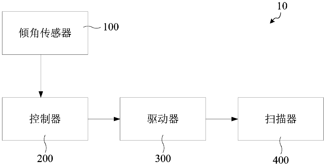
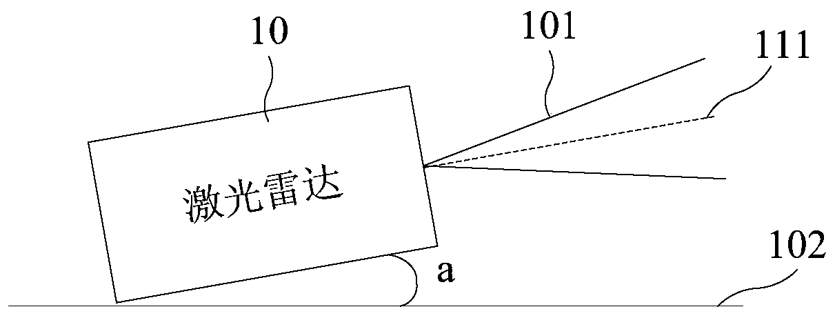
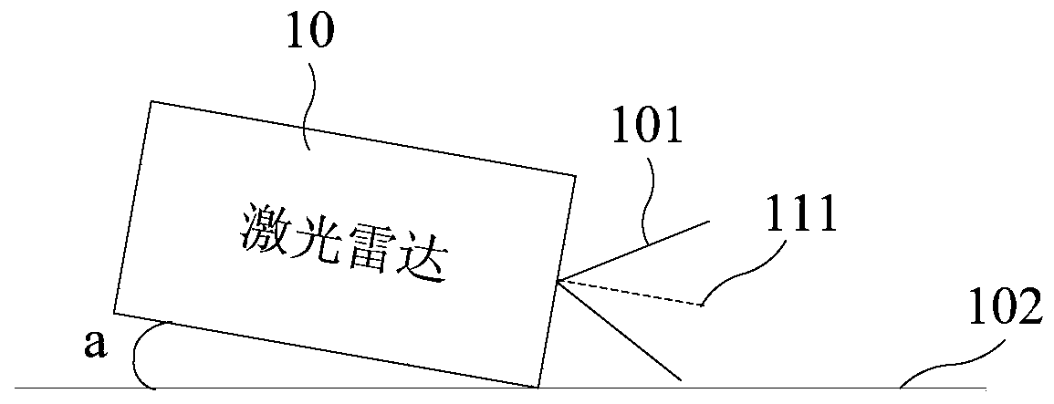
The invention discloses a laser radar, equipment and a laser radar installation angle calibration method. The laser radar comprises a tilt angle sensor, a controller, a driver and a scanner, wherein the tilt angle sensor, the controller, the driver and the scanner are sequentially connected in series; the tilt angle sensor is used for detecting an installation angle of the laser radar; the controller is used for obtaining an actual deflection angle of the scanner according to the installation angle and a target inclination angle of a laser beam emitted by the scanner, and generating a drivinginstruction carrying the actual deflection angle; and the driver is used for driving the scanner to deflect the actual deflection angle according to the driving instruction. According to the technicalscheme provided by the embodiments of the invention, the automatic compensation of an installation error of the laser radar is realized, no manual consumption is generated, the man-hour is short, andthe measurement and debugging precision is high.

Description

technical field [0001] Embodiments of the present invention relate to the technical field of laser radar, and in particular, to a laser radar, equipment, and a method for calibrating an installation angle of the laser radar. Background technique [0002] Lidar is a radar system that emits laser beams to detect characteristic quantities such as the position and speed of the target. Compared with ordinary microwave radar, because it uses laser beams, its operating frequency is much higher, and it has high resolution and concealment. Good, strong anti-interference ability, small size and light weight and other advantages. [0003] LiDAR is usually installed on a fixed plane. For example, it is installed on the top of a vehicle. Due to the influence of the installation environment and other conditions, installation errors will occur. Installation errors will affect the detection range of LiDAR, especially the pitch error. The impact is more significant. In the prior art, after ...

Claims


Application Information

Patent Timeline
Patent Type & Authority Applications(China)
IPC IPC(8): G01S17/02G01S7/481G01S7/497
Inventor 胡小波沈俭
Owner LEISHEN INTELLIGENT SYST CO LTD
Learn More