
Controller suitable for various tools and electric tool system adapted to various applications

A technology of electric tools and controllers, applied in general control systems, control/regulation systems, program control, etc., can solve the problems of reducing the weight and volume of tools, technical difficulties, etc., and achieve the effect of cost saving

Pending Publication Date: 2019-06-11
田角峰 +1
View PDF0 Cites 3 Cited by
  • Summary
  • Abstract
  • Description
  • Claims
  • Application Information

AI Technical Summary

Problems solved by technology

With the wide application of brushless motors, the life of the controller has been greatly improved, almost permanently; if multiple electric tools share a controller, it is undoubtedly a cost-saving solution, but since we have to consider how to reduce Cost, but also to ensure mutual coordination, while reducing the weight and volume of the tool, technically difficult, the industry has not yet reported a variety of power tools share a controller power tool system

Method used


Image

  • Controller suitable for various tools and electric tool system adapted to various applications
  • Controller suitable for various tools and electric tool system adapted to various applications
  • Controller suitable for various tools and electric tool system adapted to various applications

Examples


Embodiment Construction

[0035] The working principle and features of the present invention will be described below in conjunction with the accompanying drawings, and the examples given are only used to explain the present invention, not to limit the present invention.

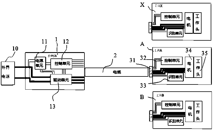
[0036] Such as figure 1 as shown, figure 1 It is a schematic diagram of the electric tool system of the present invention; it includes a controller 1, and various electric tools A, B, X; and a cable 2 for connecting the controller and the electric tool, and the electric tool A includes a motor 34, a control unit 32, A working head 35 , an identification unit 33 and a quick joint 31 , the controller includes a power supply unit 11 connected to an external power supply 10 , a control unit 12 and a drive unit 13 . The power supply unit provides energy for the control system; the external power supply 10 can be a lithium battery pack, a lead-acid battery pack, or a DC power supply.

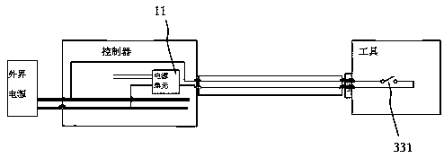
[0037] Such as image 3 As shown, after plugging in ...


PUM


Abstract

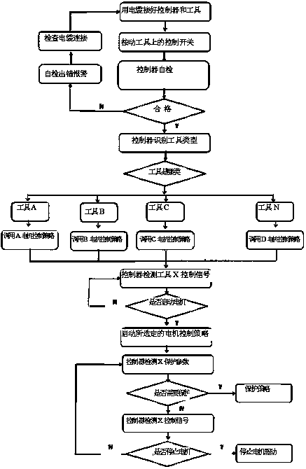
The invention relates to an electric tool system adapted to various applications. The electric tool system comprises more than one electric tool, a controller and a cable for connecting the tool and the controller; the tool comprises a working head, a motor, an identification unit and a quick-release connector; the controller comprises a power supply unit, a driving unit and a control unit; more than one motor control strategy matching the tool types is built in the driving unit; the controller also comprises a program executing the following steps that: a control unit in the controller detects the identification unit in the tool to obtain tool type information; the driving unit selects the motor control strategy corresponding to the tool type; the control unit in the controller monitors control signals from the electric tool; and the driving unit sends signals for startup, speed regulation, reversal or shut-down to the motor according to the motor control strategy. According to the scheme of the invention, a plurality of electric tools can share one controller in different times, and thus the cost can be saved.

Description

technical field [0001] The invention relates to a controller suitable for various tools and an electric tool system suitable for various applications. Background technique [0002] With the development of lithium battery technology and the extensive application and popularization of mobile portable power supplies, electric tools have gradually entered farms, forestry, public security and families. For agricultural and forestry applications, operators will use different power tools in different seasons and different stages; even at different times in the same stage, operators need to use multiple tools. For example, brush cutters (grass trimmers), micro tillage machines, electric drills and electric chain saws are commonly used in spring or sowing stages; pruning shears (hedge trimmers), electric scissors, hair dryers (sprayers), etc. are used in plant growth stages; Extensive use of brush cutters (grass trimmers), micro tillage machines, electric scissors, etc.; extensive u...

Claims


Application Information

Patent Timeline
Patent Type & Authority Applications(China)
IPC IPC(8): G05B19/042
Inventor 田角峰田璐璐
Owner 田角峰
Learn More