
Method for manufacturing heat dissipation device

A technology of heat dissipation device and manufacturing method, which is applied in the direction of cooling/ventilation/heating transformation, indirect heat exchanger, heat exchange equipment, etc., which can solve the problems of unreliable sealing of defective products, inflexibility of use, and increase of manufacturing cost of waste materials, etc.

Active Publication Date: 2019-06-11
ASIA VITAL COMPONENTS SHENZHEN CO LTD
View PDF5 Cites 3 Cited by
  • Summary
  • Abstract
  • Description
  • Claims
  • Application Information

AI Technical Summary

Problems solved by technology

[0004] The above-mentioned cooling device mainly achieves heat exchange through the vapor-liquid exchange of internal working liquid boiling and condensing at low temperature in a vacuum airtight chamber. Most heat pipes and vapor chambers are easily limited by the space used, so the shape and thickness are different. Restricted, only the size of general regulations can be used, and it is quite inflexible in use
[0005] However, in the existing vapor chamber, two plates are superimposed and sealed to form an airtight chamber, and the heat pipe is formed by sealing both ends of a pipe body to form an airtight chamber, and the airtight chamber is sealed. Vacuumize the chamber and fill it with working liquid. Whether it is a vapor chamber or a heat pipe, it is most likely to cause poor airtightness during the edge banding operation during the process and cause air leakage. In order to reserve a closed end or edge, it will Produces ineffective areas that cannot work, which wastes materials and increases manufacturing costs
[0006] Existing manufacturing methods for manufacturing heat pipes or vapor chambers require the purchase of multiple pieces of equipment, and each unit is independently manufactured by each piece of equipment (such as the outer tube of the heat pipe, the upper and lower plates of the chamber) before proceeding to the next step. Stage work, and at least one capillary structure (such as sintered powder, braided mesh, groove) is provided in the airtight chamber of the vapor chamber and the heat pipe, but the aforementioned capillary structure must go through at least one processing step on the inner wall of the chamber (sintering or welding or diffusion bonding or drawing or laser) can only set the capillary structure on the inner wall of the chamber, but if the capillary structure is made of a woven mesh, it will not be able to be completely ironed on the inner wall of the chamber. , when the capillary structure cannot be ironed on the inner wall of the chamber, it will cause the problem of poor capillary force, and because the existing vapor chamber is a structural member composed of two plates superimposed on each other, it is easy to design and manufacture Restricted or complicated process steps
[0007] Therefore, in the existing manufacturing method, it is necessary to complete each individual element separately and then combine each unit, or perform other processing or combination, and the degree of combination of each unit or the airtight chamber is likely to be inaccurately combined or not properly closed. resulting in defective products

Method used


Image

  • Method for manufacturing heat dissipation device
  • Method for manufacturing heat dissipation device
  • Method for manufacturing heat dissipation device

Examples


Embodiment Construction

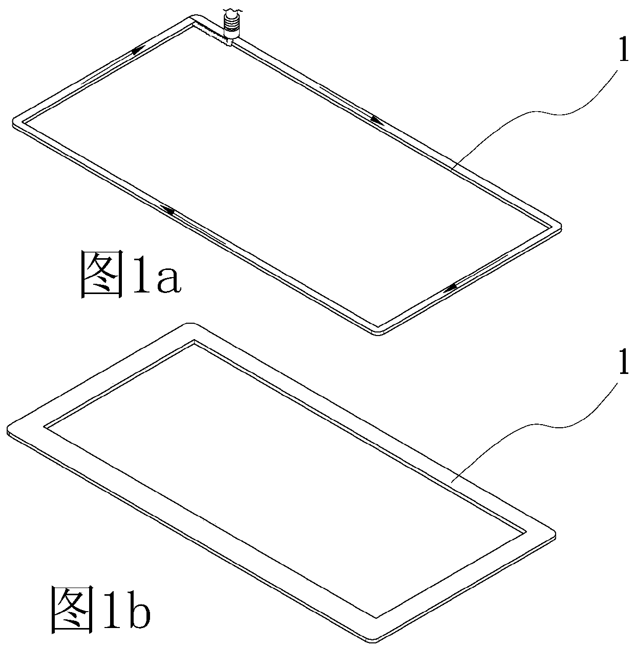
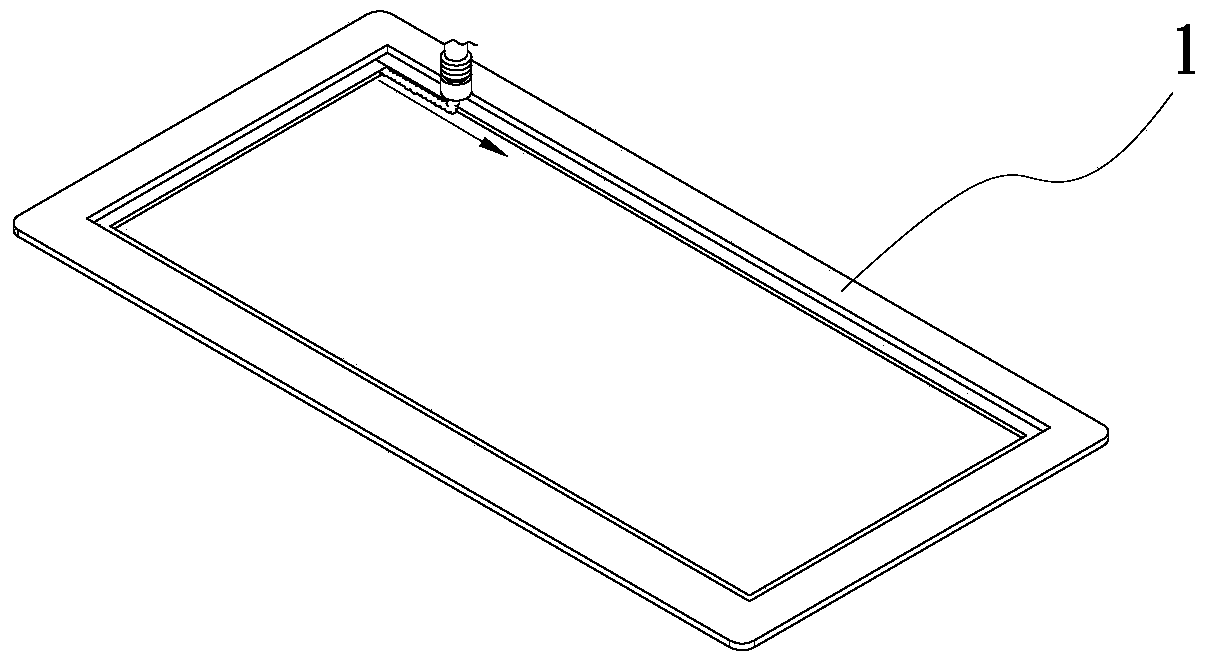
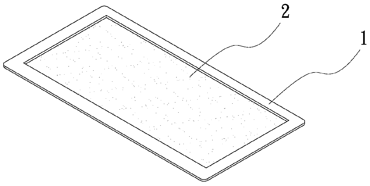
[0071] The heat dissipation device of the present invention is based on the concept of building a complete structure layer by layer or part by part in a way from scratch. The manufacturing method from scratch is mainly through 3D printing or electrochemical processing or printing or spraying. way or any two or more of them to be manufactured together, to form the structure of the present invention, it must first form a main base carrier, and then build other secondary structural components or structures layer by layer on the main base carrier body, and then form a one-piece structure.

[0072] see Figure 1a , Figure 1b , Figure 1c , Figure 1d , is a combination cross-sectional view of the first embodiment of the heat dissipation device of the present invention. As shown in the figure, the element as the main basic carrier in this embodiment is the lower plate of the vapor chamber, which is hereinafter referred to as a first unit in this embodiment. Body 1, the surface o...


PUM


Abstract

The present invention provides a method for manufacturing a head dissipation device. The heat dissipation device includes a first basic structural body having a wick structure formed on one side surface thereof; and the first basic structural body and the wick structure are structural bodies formed layer by layer. Two pieces of first basic structural bodies can be correspondingly closed together to construct a heat dissipation device internally defining an airtight chamber. In this manner, the heat dissipation device can be designed in a more flexible manner.

Description

technical field [0001] The invention relates to a method for manufacturing a heat sink, in particular to a method for manufacturing a heat sink with an integral structure composed of multiple laminated layers. Background technique [0002] As the efficiency of current electronic equipment improves, the electronic components used for signal processing and calculation also generate higher heat than the previous electronic components. The most commonly used general heat dissipation components include heat pipes, radiators, vapor chambers and other components. , and further increase the heat dissipation performance by directly contacting the electronic components that will generate heat, so as to prevent the electronic components from being burned due to excessive temperature. [0003] Vapor chambers, heat pipes, and loop heat pipes are common heat dissipation devices. The above-mentioned vapor chambers, heat pipes, and loop heat pipes mainly achieve the effect of heat conductio...

Claims


Application Information

Patent Timeline
Patent Type & Authority Applications(China)
IPC IPC(8): H05K7/20
CPCH05K7/20336C25D7/00F28D15/0233F28D15/0266H01L23/3731H01L23/3736H01L23/3737H01L23/427C23C24/08C25D1/00C23C18/31B23P15/26F28D15/046B33Y80/00F28F21/065F28D15/043F28F21/083F28F21/084F28F21/085F28F21/086F28F21/087F28D15/06F28F21/04
Inventor 江贵凤
Owner ASIA VITAL COMPONENTS SHENZHEN CO LTD
Learn More